Install a hot-swap drive
Follow instructions in this section to install a hot-swap drive.
About this task
Attention
- To avoid damage to the drive connectors, make sure that the node top cover is installed and fully closed whenever installing or removing a drive.
- To make sure that there is adequate system cooling, do not operate the node for more than two minutes without either a drive or a filler installed in each drive bay.
- The drive bays are numbered in installation ordering (starting from number “0”). Follow this sequential order of the drive bays when installing a drive. To locate the drive bays of the node, see the pull-out information tab on the front of the node or Node front view.
- The following notes describe the type of drives that the node supports and other information that must be considered for drive installation.
- Locate the documentation that comes with the drive and follow those instructions in addition to the instructions in this topic.
- The drive cage supports up to six 7mm or 15mm 2.5-inch SAS/SATA/NVMe solid-state drives.
- The electromagnetic interference (EMI) integrity and cooling of the node are protected by having all bays and PCI and PCIe slots covered or occupied. When installing a drive, PCI, or PCIe adapter, save the EMC shield and filler panel from the bay or PCI or PCIe adapter slot cover in the event that you later remove the device.
- For a complete list of supported optional devices for the node, see Lenovo ServerProven website.
For configurations with one processor and one PCIe riser assembly, only up to two NVMe SSDs are supported.
Firmware and driver download: You might need to update the firmware or driver after replacing a component.
Go to Drivers and Software download website for ThinkSystem SD550 V3 to see the latest firmware and driver updates for your server.
Go to Update the firmware for more information on firmware updating tools.
Procedure
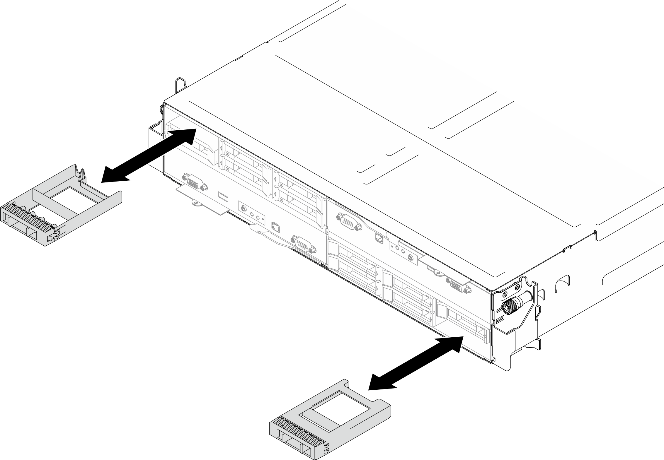
- If the drive bay contains a filler, pull the release lever on the filler and slide it out of the bay.Figure 1. Replacement of a drive filler
- Install the hot-swap drive.
 Make sure that the drive handle is in the open position; then, align the drive with the guide rails in the bay and gently push the drive into the bay until the drive stops.
 Pivot the drive handle to the fully closed position until the handle latch clicks into place.Note
- Depending on the specific configuration, the hot-swap drive to be installed may be a 7 mm or 15 mm 2.5-inch solid-state drive. The installation procedures are the same.
- In the right bay (seen from the front), the node must be installed upside down. From this node, the drive to be installed is also upside down, but the installation procedures are the same.
Figure 2. Installation of a 7mm solid-state drive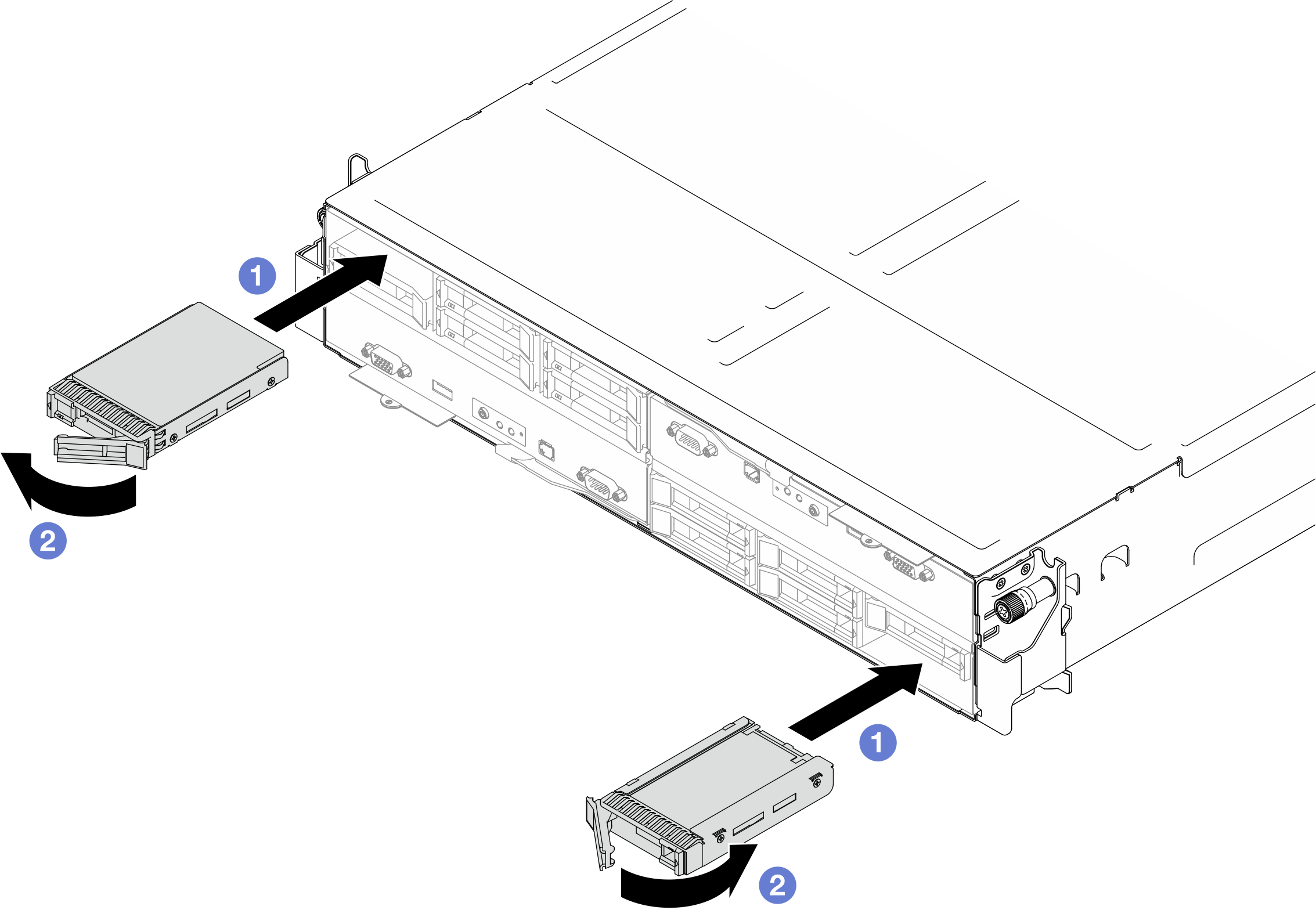 Figure 3. Installation of a 15mm solid-state drive
After you finish
Check the drive status LED to verify that the drive is operating correctly (see Drive LEDs). If the yellow drive status LED of a drive is lit continuously, that drive is faulty and must be replaced. If the green drive activity LED is flashing, the drive is being accessed.
Demo video
Give documentation feedback