Install the carrier base board (CBB)
Use this information to install the carrier base board (CBB). This procedure is trained technician only.
About this task
Required tools
Make sure you have the required tools listed below in hand to properly replace the component.
Water loop kits
SD650-I V3 Water loop service kit (03KH870)
SD650-I V3 Water loop putty pad kit (03LD670)
Screws and screwdrivers
Prepare the following screwdrivers to ensure you can install and remove corresponding screws properly.Screwdriver Type Screw Type Torx T10 head screwdriver Torx T10 screw Phillips #1 head screwdriver Phillips #1 screw Phillips #2 head screwdriver Phillips #2 screw
To identify the gap pad/putty pad location and orientation, see Gap pad and putty pad identification and location.
Before replacing the gap pad/putty pad, gently clean the interface plate or the hardware surface with an alcohol cleaning pad.
Hold the gap pad/putty pad carefully to avoid deformation. Make sure no screw hole or opening is blocked by the gap pad/putty pad material.
Do not use expired putty pad. Check the expiry date on putty pad package. If the putty pads are expired, acquire new ones to properly replace them.
Read Installation Guidelines and Safety inspection checklist to ensure that you work safely.
Turn off the corresponding DWC tray that you are going to perform the task on.
To avoid damaging the water loop, always use the water loop carrier when removing, installing or folding the water loop.
- When removing the new carrier base board from the package box,
Hold the long sides of the carrier base board with two hands.
- Make sure to hold the carrier base board gently. Avoid applying pressure or force to it.
- When installing the carrier base board to the node, avoid touching the connectors on the carrier base board. Be careful not to damage any surrounding components inside the node.
Figure 1. Removing carrier base board from the package box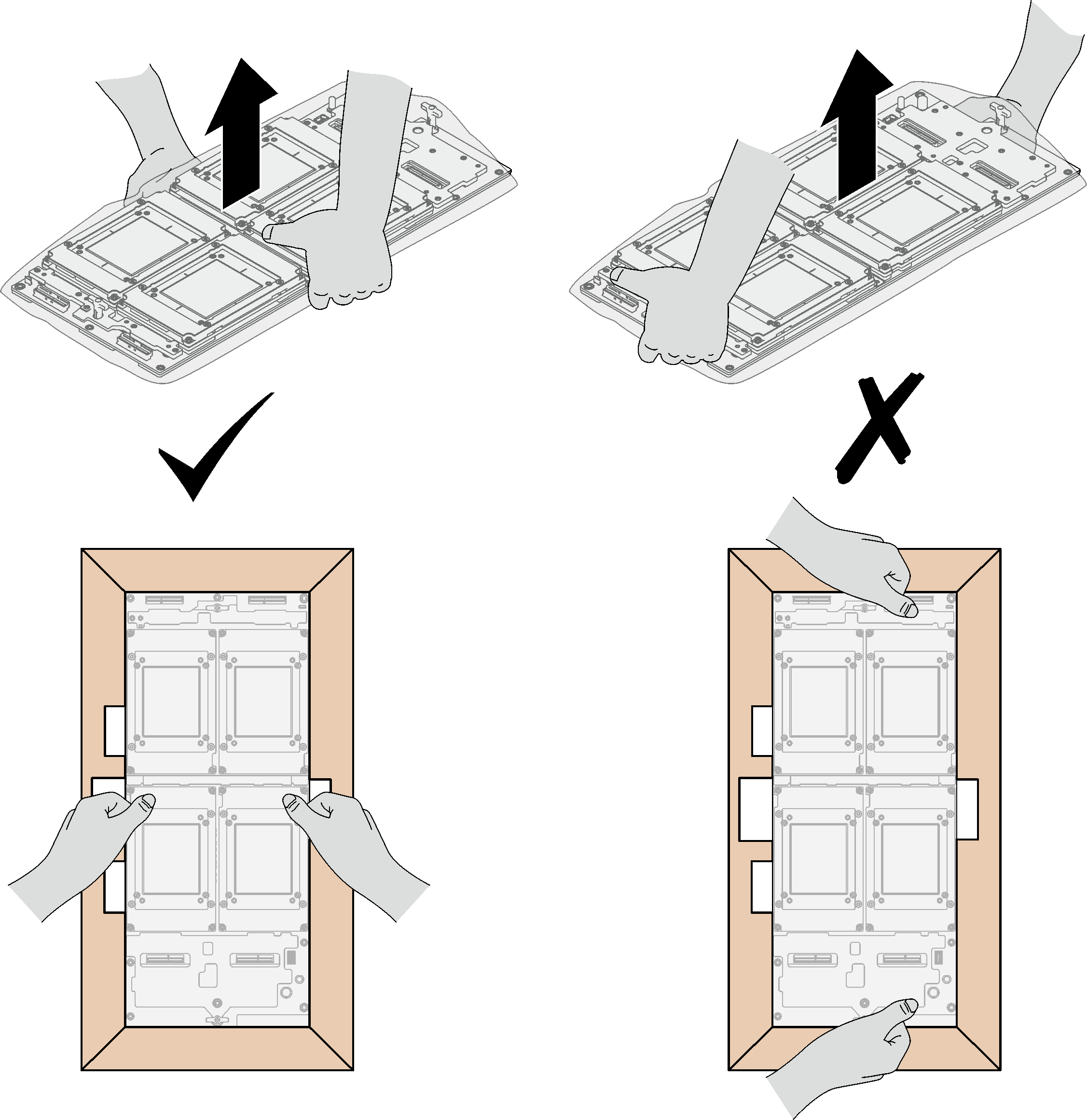
Once the carrier base board is removed from the plastic protective bag, hold two handles with both hands to move the carrier base board.
Figure 2. Removing carrier base board from the package box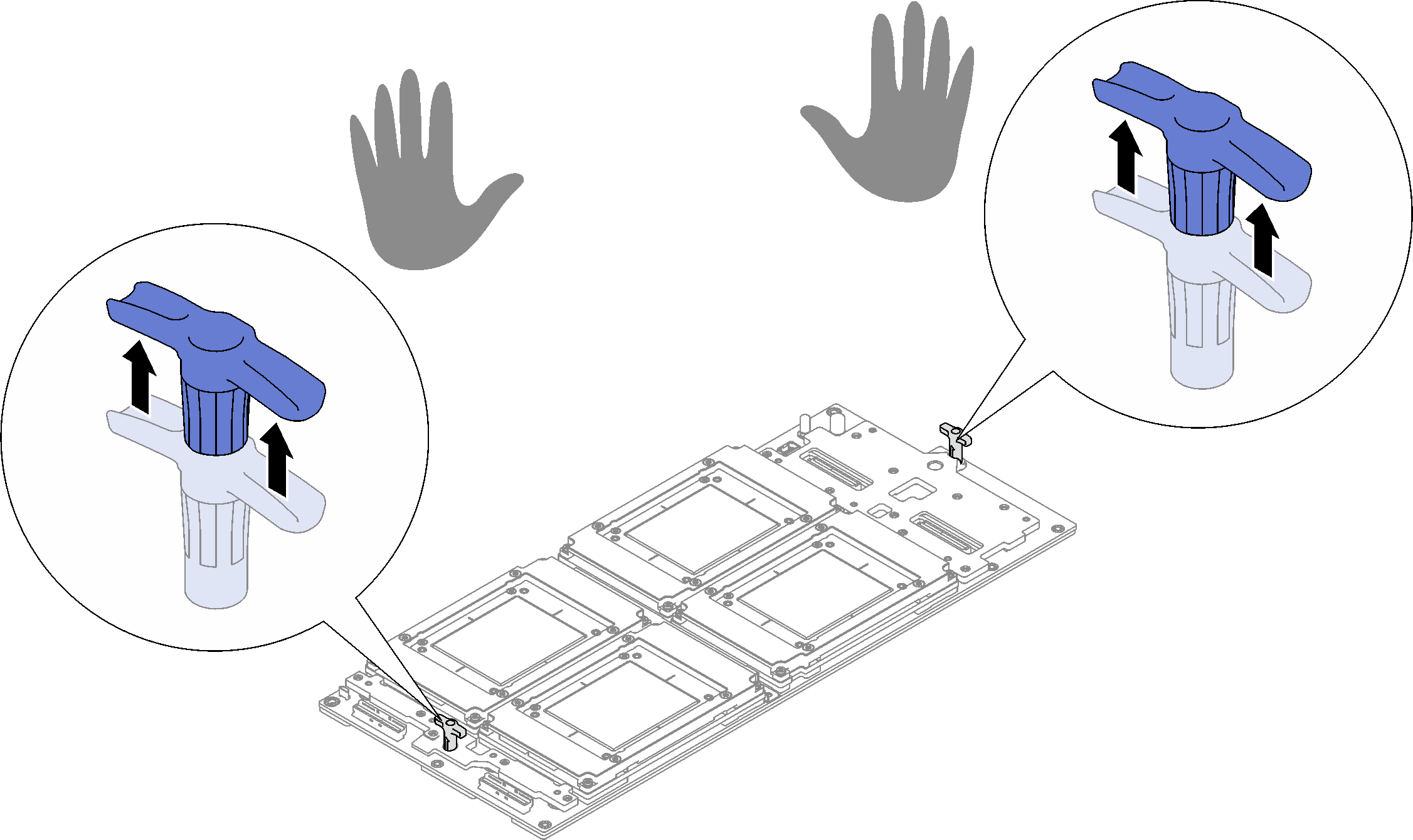
Requirements for proper CBB installation
- Update Retimer firmware via XCC Web GUI or LXCE OneCLI with the following command, where FW_FILE_NAME is the Retimer firmware file name.
OneCli update flash --nocompare --includeid FW_FILE_NAME --checkdevice --dir /flash/ --output /flash/resultAfter updating Retimer firmware, reboot the system.
Update carrier base board firmware by updating XCC firmware, see Lenovo XClarity Controller portal page.
After updating XCC firmware, perform virtual reseat to optimize system, see SMM2 User Guide.
Go to Drivers and Software download website for ThinkSystem SD650-I V3 to see the latest firmware and driver updates for your server.
Go to Update the firmware for more information on firmware updating tools.
Procedure
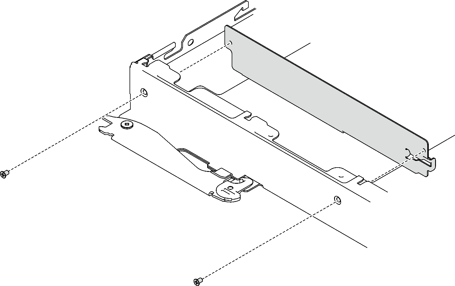
- (Optional) If you are replacing hot-swap power supplies with DWC power supplies, install the front cover to the node with two screws.
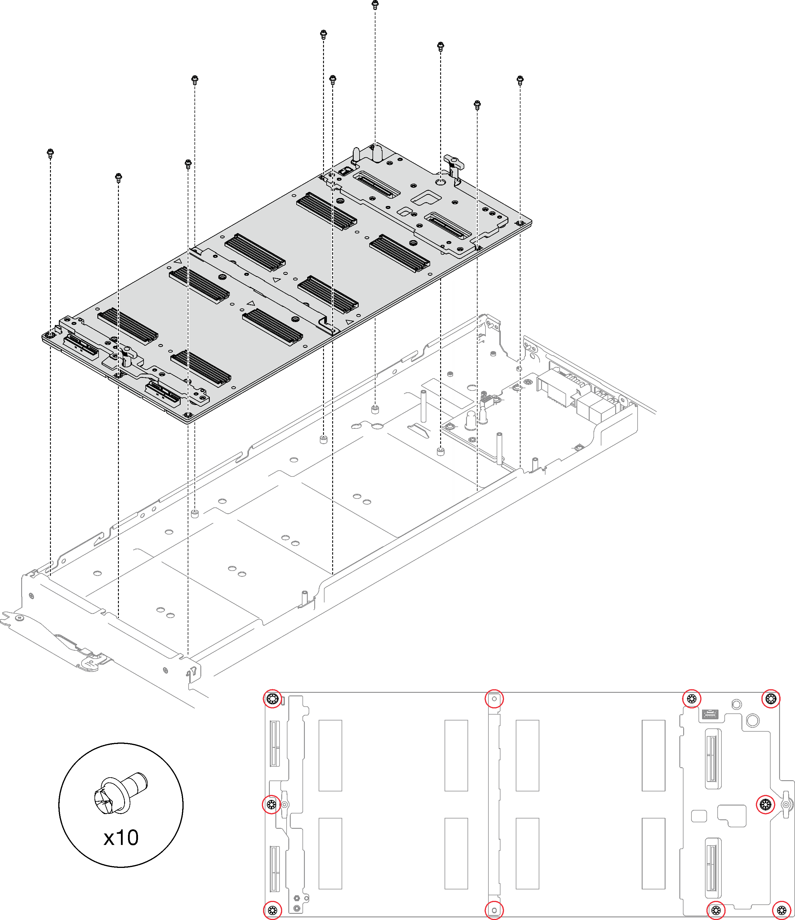
- Gently place the carrier base board down and install the ten Phillips #1 screws with a torque screwdriver set to the proper torque. NoteFor reference, the torque required for the screws to be fully tightened/removed is 5.0+/- 0.5 lbf-in, 0.55+/- 0.05 N-M.AttentionWhen you install the carrier base board to the node, avoid touching the connectors on the carrier base board. Be careful not to damage any surrounding components inside the node.Figure 4. Carrier base board installation
- Install all four GPU OAMs to the carrier base board. Gently place the GPU OAM down on the carrier base board (CBB); then, install the four Torx T15 screws with a torque screwdriver set to the proper torque.AttentionFollow the three-step GPU OAM installation method:
When tightening the screws, follow the sequence shown in the picture below.
First, set the torque screwdriver to 0.0981 N-M (0.868 lbf.in) to slightly tighten the screws.
Second, set the torque screwdriver to 0.8829 N-M (7.8 lbf.in) to fully tighten the screws.
Lastly, set the torque screwdriver to 0.8829 N-M (7.8 lbf.in), and fasten each screw to ensure that all screws are fully tightened.
Figure 5. Screw tightening sequence for GPU OAM installation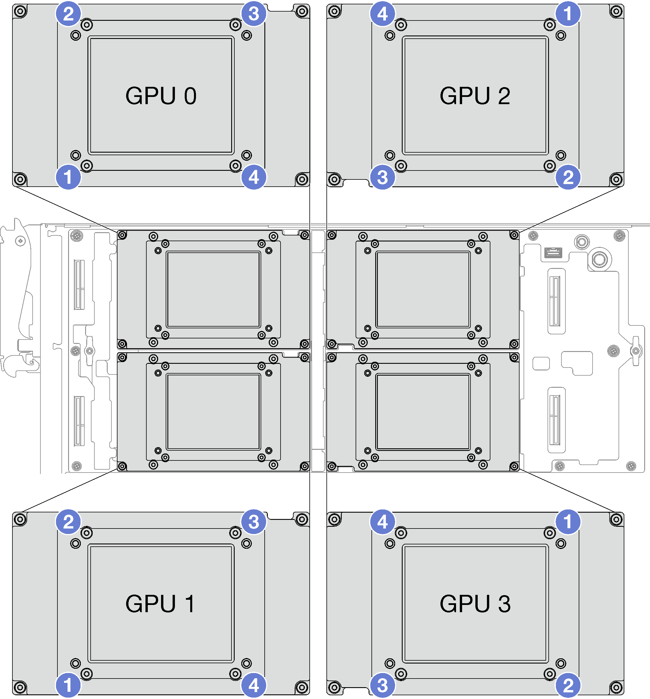
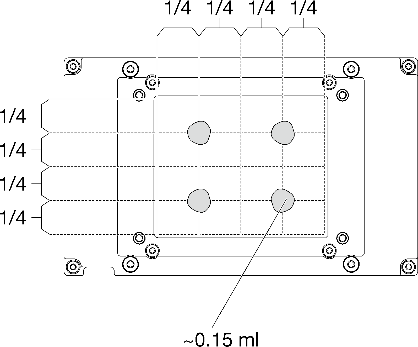
- Apply the thermal grease on the top of the four GPU OAMs with syringe by forming four dots spaced as shown, while each dot consists of about 0.15 ml of thermal grease.Figure 6. Thermal grease application
- Check the gap pads on the water loop, if any of them are damaged or detached, replace them with the new ones.Figure 7. Water loop gap pads
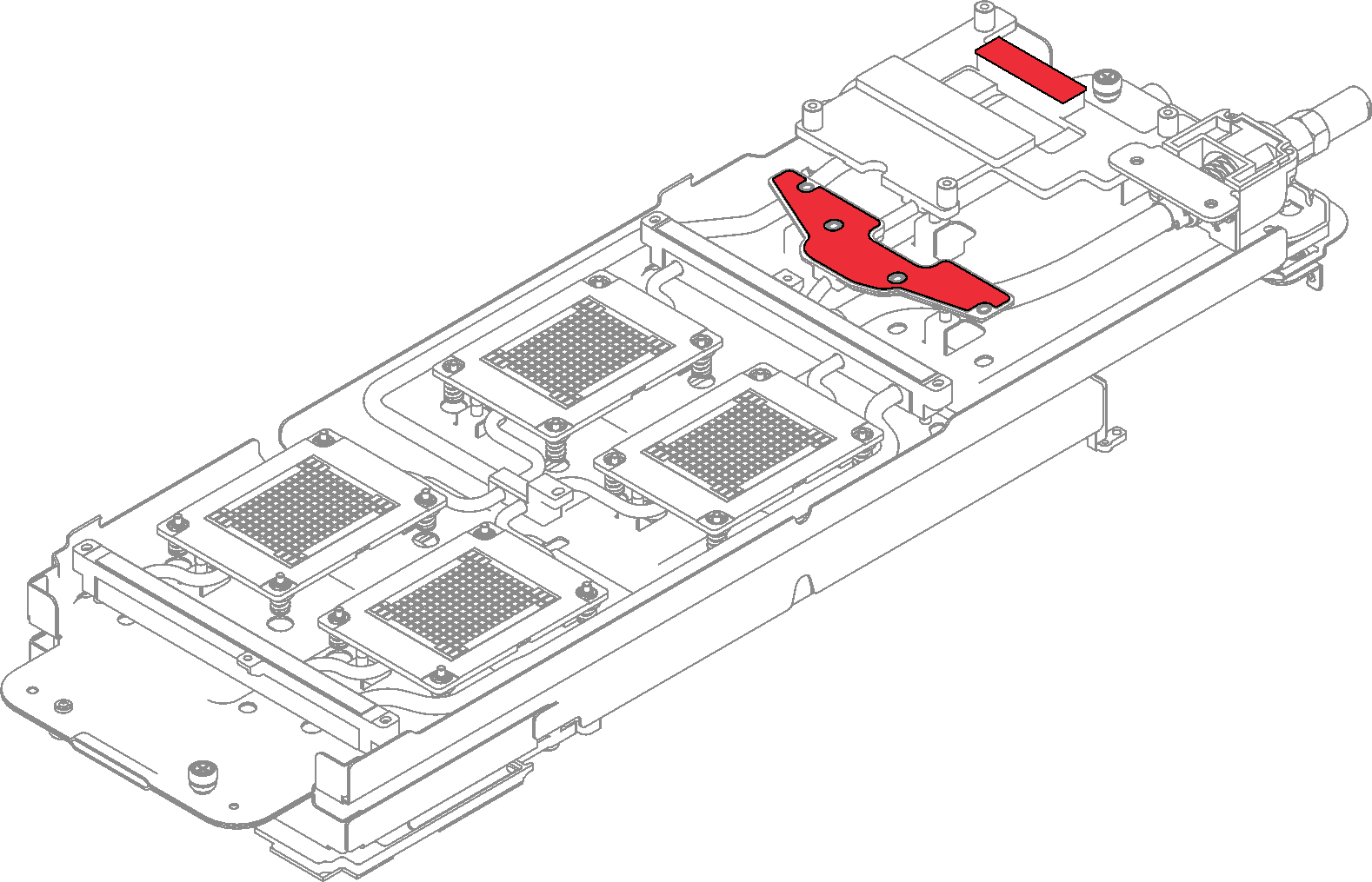
Make sure to follow Gap pad/putty pad replacement guidelines.
- Replace the putty pads on the water loop with new ones.NoteWhen attaching the putty pads on GPU cold plate, align the putty pads with the markings on the GPU cold plate.Figure 8. Putty pad locations
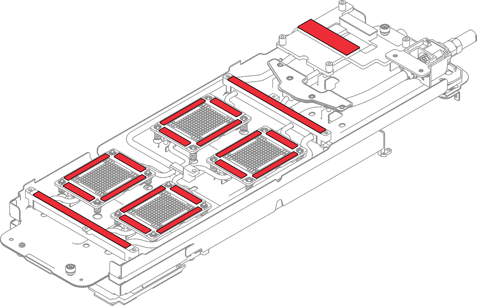
Make sure to follow Gap pad/putty pad replacement guidelines.
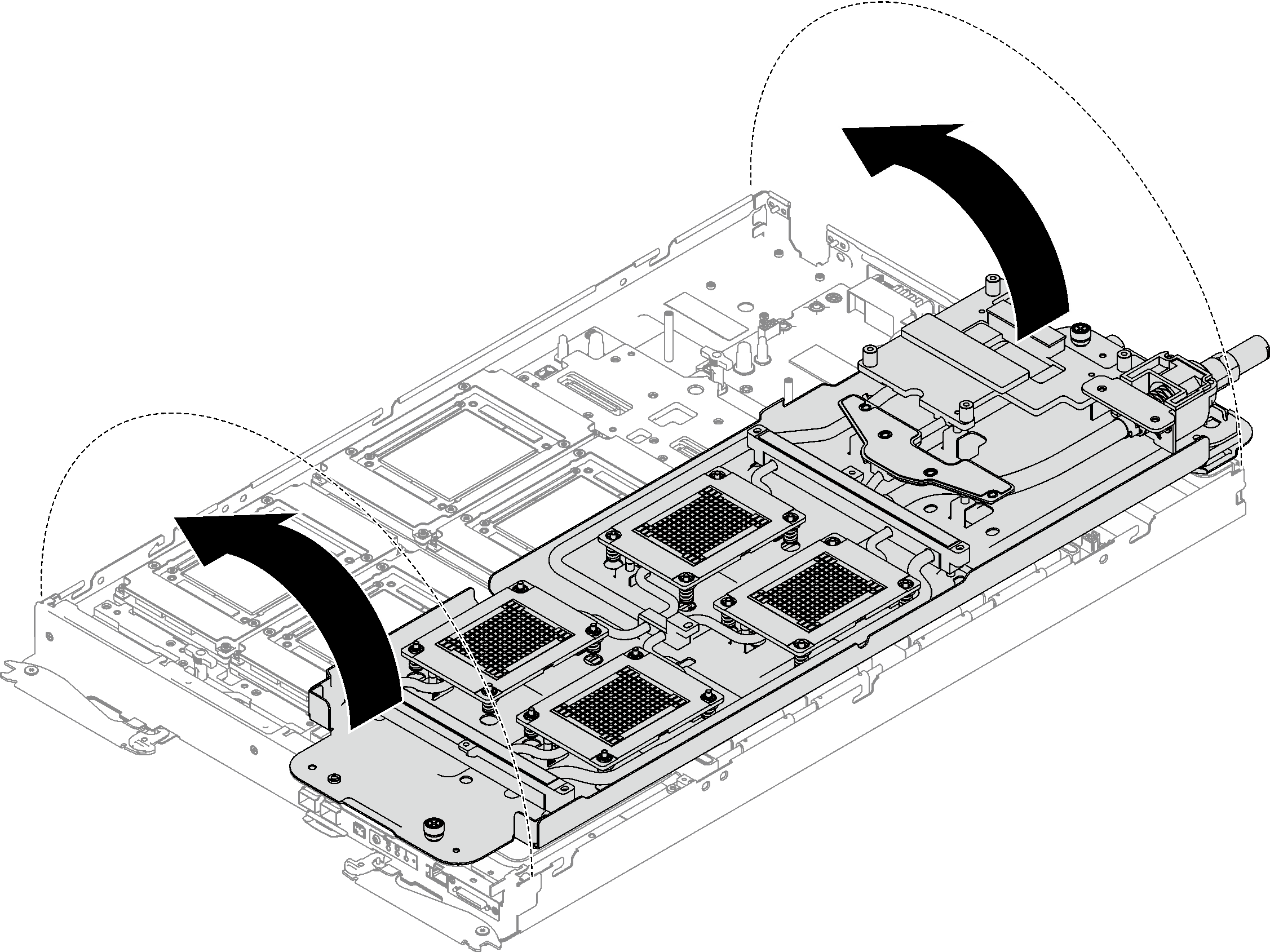
- Unfold and install the water loop as shown.Figure 9. Water loop installation
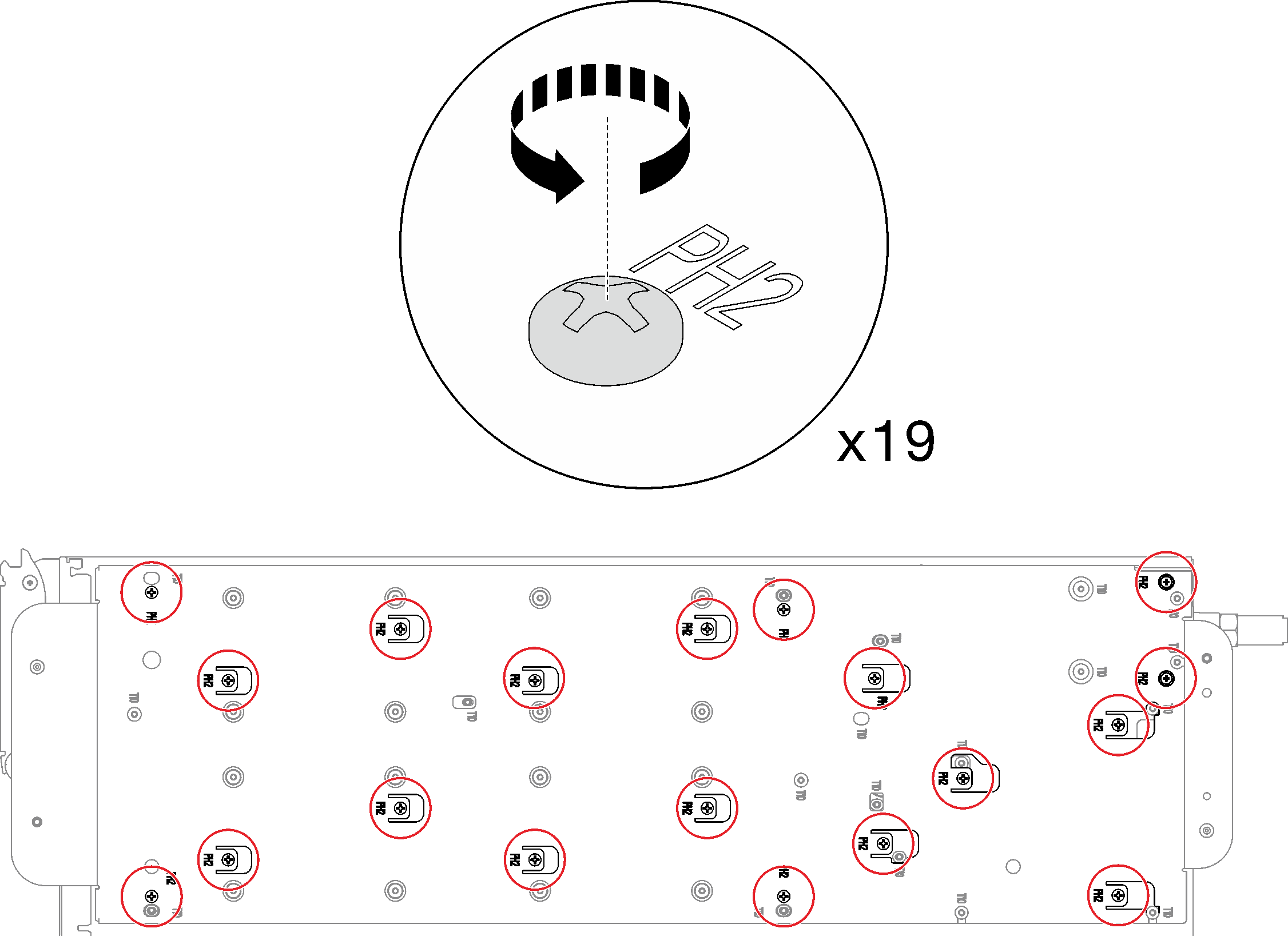
- Loosen water loop carrier screws (19x Phillips #2 screws).Figure 10. Loosening water loop carrier screws
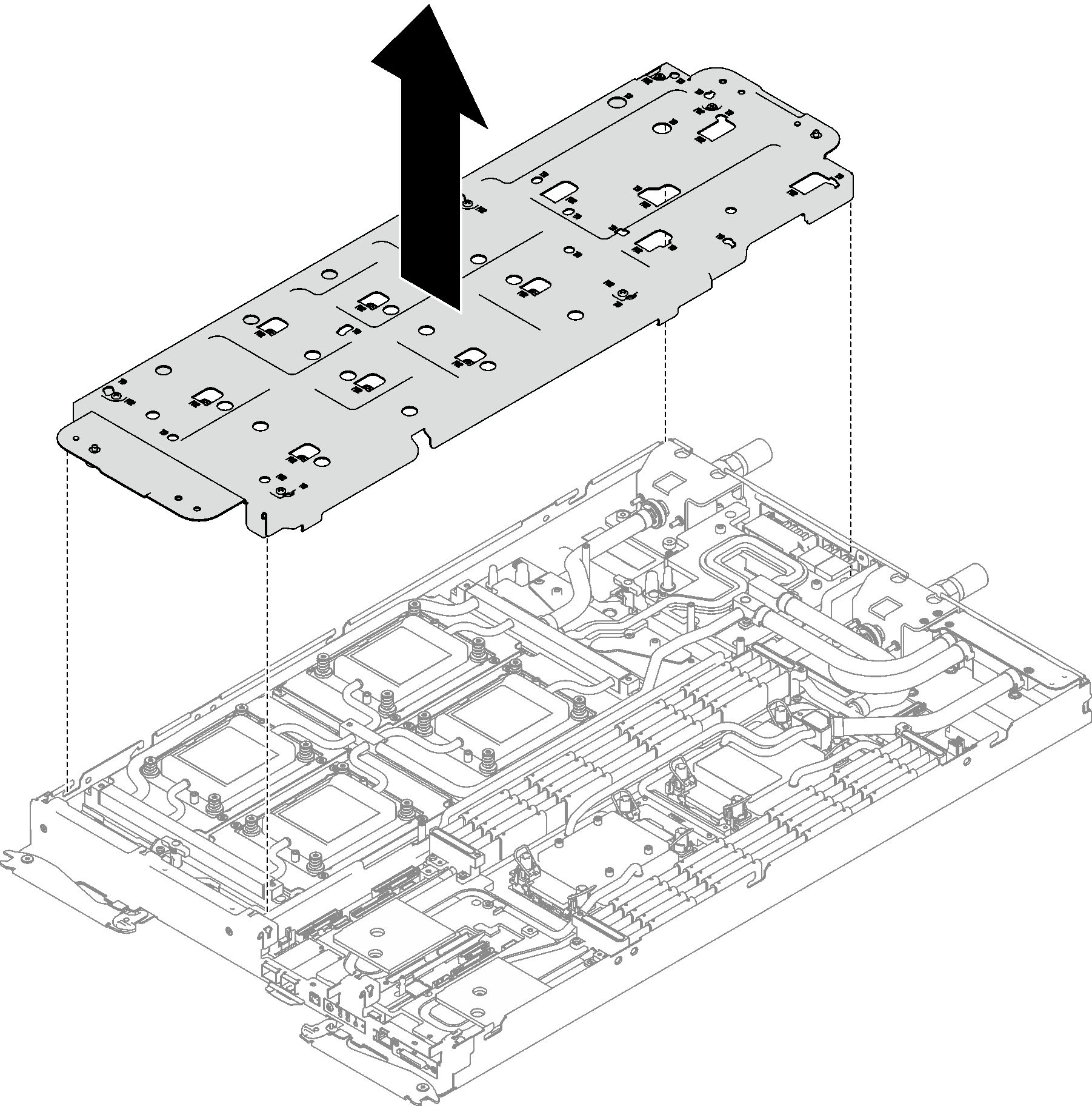
- Carefully lift the water loop carrier up and away from the water loop.Figure 11. Water loop carrier removal
- Install water loop screws (14x Torx T10 screws) with a torque screwdriver set to the proper torque.NoteFor reference, the torque required for the screws to be fully tightened/removed is 5.0+/- 0.5 lbf-in, 0.55+/- 0.05 N-M.Figure 12. Water loop screws installation

- Install the following screws to secure the quick connect.
Two Torx T10 screws to secure the quick connect.
Four Torx T10 screws on the rear of the node.
Figure 13. Quick connect screw installation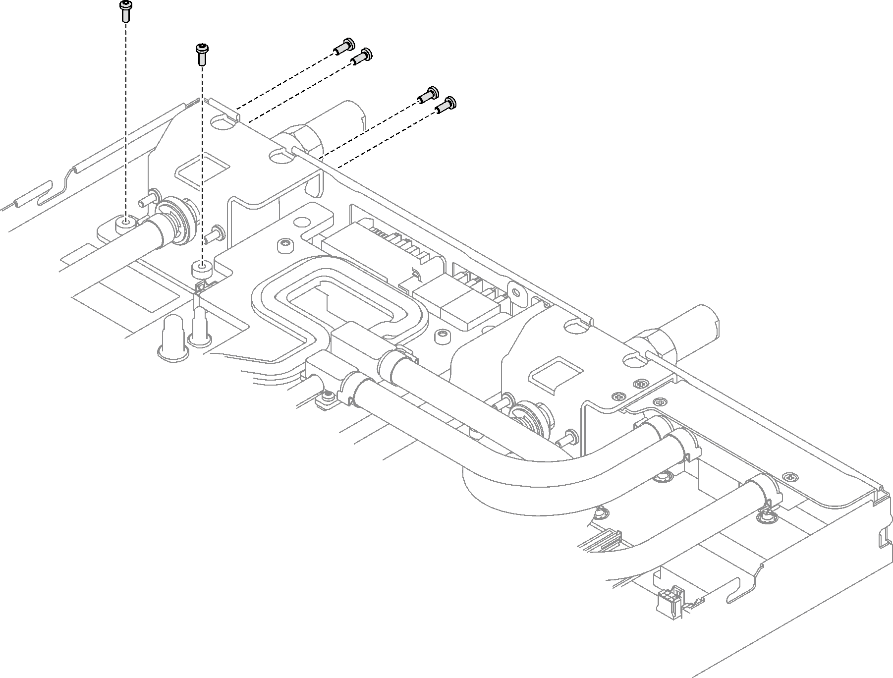
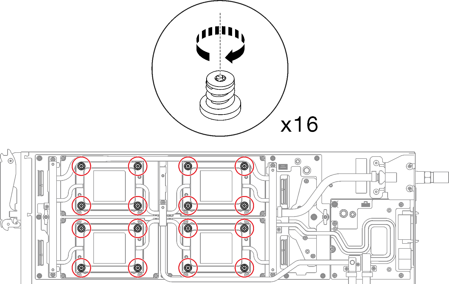
- Install the GPU OAM cold plate screws (16x Torx 15 screws).Figure 14. GPU OAM cold plate screw installation
 Push down the GPU OAM cold plate with your palm to reduce the gap between the GPU OAM cold plate and the GPU OAM.
 Press the torque screwdriver against the screw so that the screw is engaged with the GPU OAM.
 Follow the screw sequence specified on the GPU OAM cold plate label, and fasten each screw for 720 degrees with a torque screwdriver set to the proper torque and rpm.NoteFor reference, the torque required for the screws to be fully tightened/removed is 0.9 +/-0.06 newton-meters, 8+/- 0.5 inch-pounds. The rpm setting is 200 rpm low-speed.Figure 15. Fastening GPU OAM cold plate screws for 720 degrees
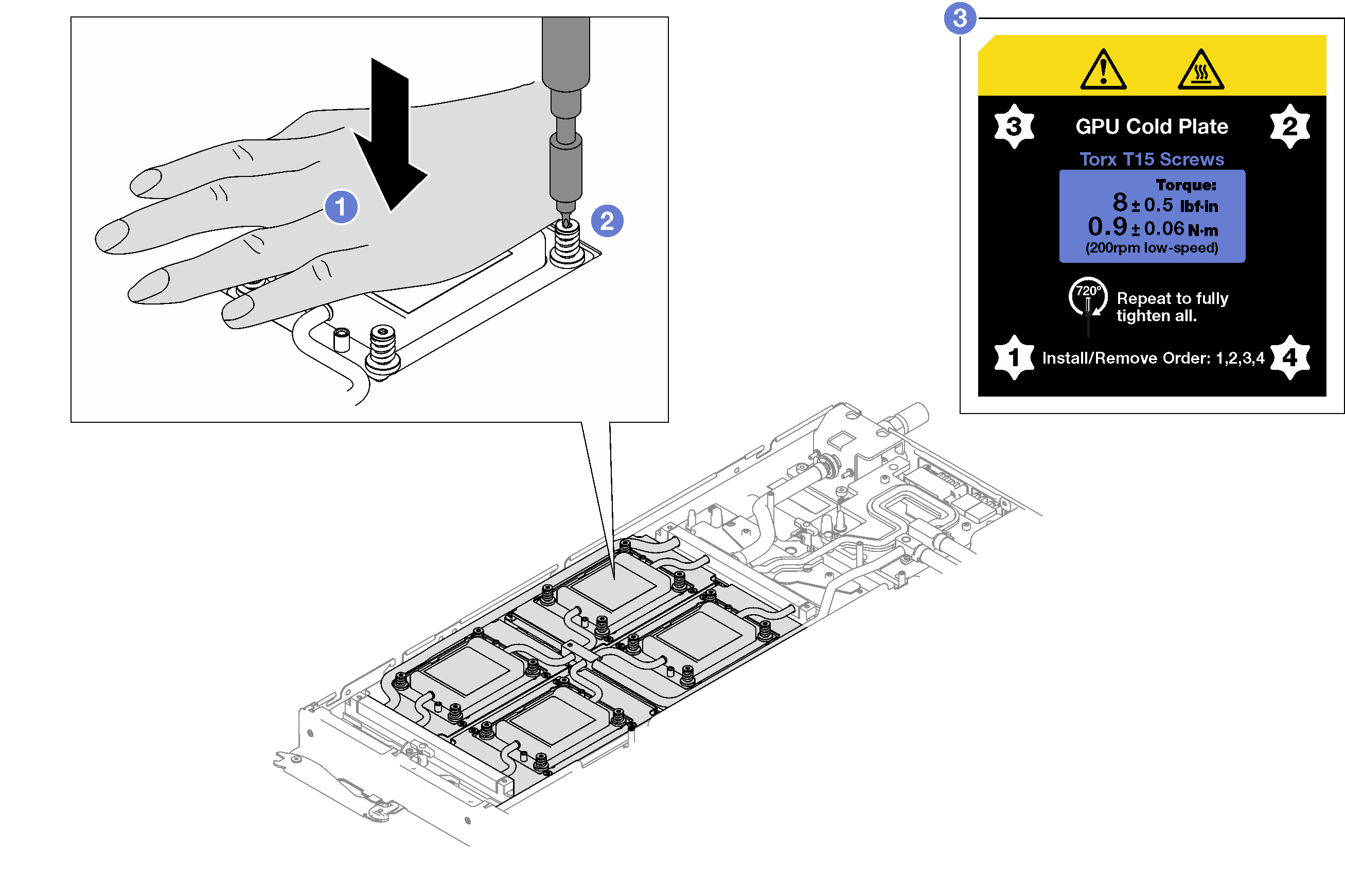
 Make sure that the GPU OAM cold plate is lowered into the node and its surface is flat without tilting. If the GPU OAM cold plate is tilted, unfasten the screws, and repeat Step 1 to Step 3.
 Repeat Step 3 until the screws are fully tightened.
-
 Make sure the height of each screw is 11.5±0.3 millimeter (0.45±0.01 inch) and is fully compressed. If not, repeat the GPU OAM cold plate installation steps.Figure 16. Height of properly installed GPU OAM cold plate screw
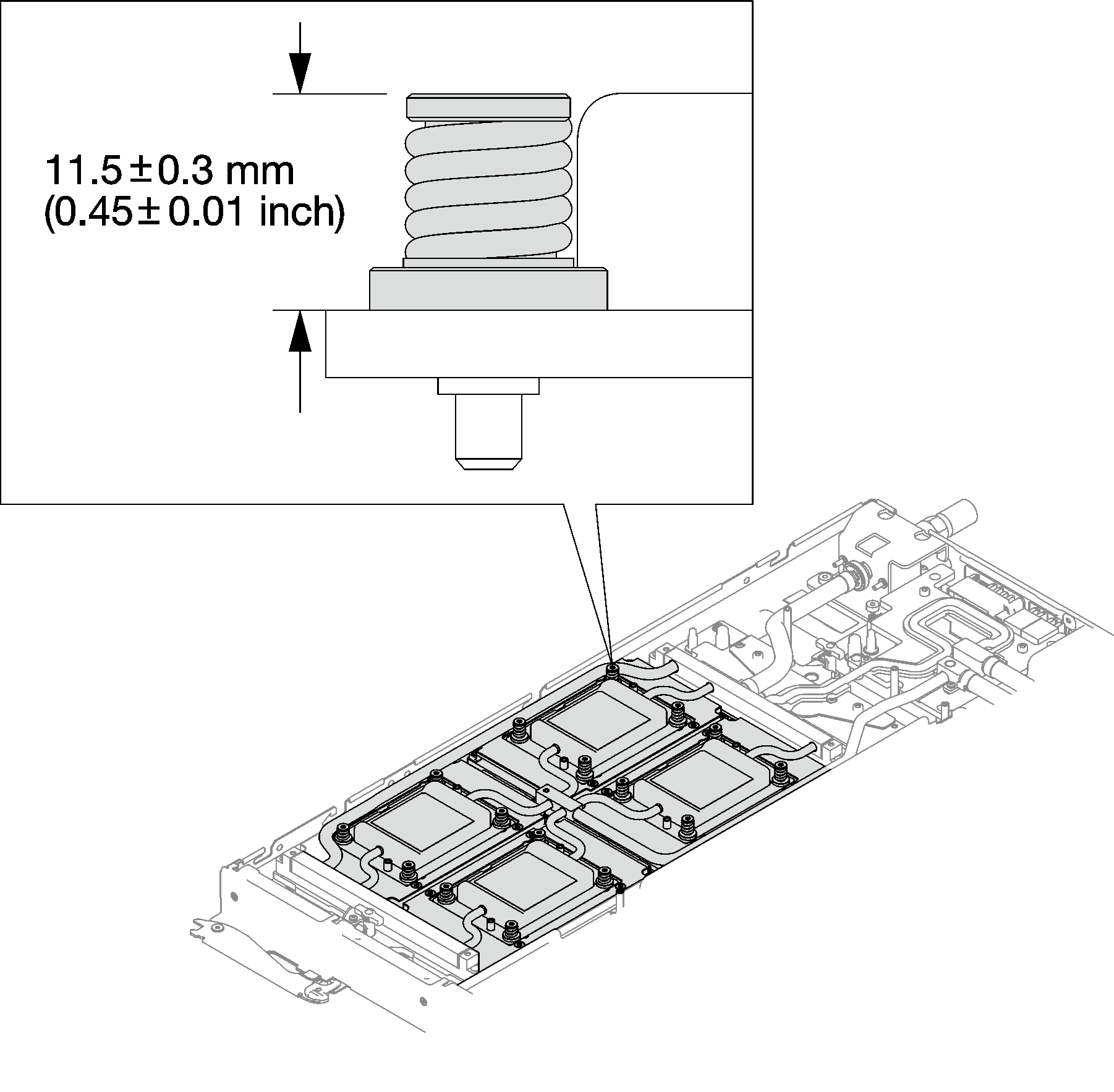
Connect and route the cables in the tray. See GPU node cable routing.
Install the cross braces. See Install the cross braces.
Install the tray cover. See Install the tray cover.
Install the tray into the enclosure. See Install a DWC tray in the enclosure.
- Connect all required external cables to the solution.NoteUse extra force to connect QSFP cables to the solution.
Check the power LED on each node to make sure it changes from fast blink to slow blink to indicate all nodes are ready to be powered on.
After installing the CBB, it is required to update carrier base board firmware (included in XCC firmware) and Retimer firmware. Latest firmware can be found at Drivers and Software download website for ThinkSystem SD650-I V3.
- Update Retimer firmware via XCC Web GUI or LXCE OneCLI with the following command, where FW_FILE_NAME is the Retimer firmware file name.
OneCli update flash --nocompare --includeid FW_FILE_NAME --checkdevice --dir /flash/ --output /flash/result Update carrier base board firmware by updating XCC firmware, see Lenovo XClarity Controller portal page.