Remove the manifold
Use this information to remove the manifold.
About this task
The water might cause irritation to the skin and eyes. Avoid direct contact with the lubricant.

Read Installation Guidelines and Safety inspection checklist to ensure that you work safely.
Ensure proper handling procedures are followed when working with any chemically treated water used in the compute rack cooling system. Ensure that material safety data sheets (MSDS) and safety information are provided by the water chemical treatment supplier and that proper personal protective equipment (PPE) is available as recommended by the water chemical treatment supplier. Protective gloves and eyewear may be recommended as a precaution.
The task in this section requires two or more people.
- A video of this procedure is available at YouTube.
Procedure
- At the front of the rack, close both Eaton ball valves.Figure 1. Eaton ball valves closed
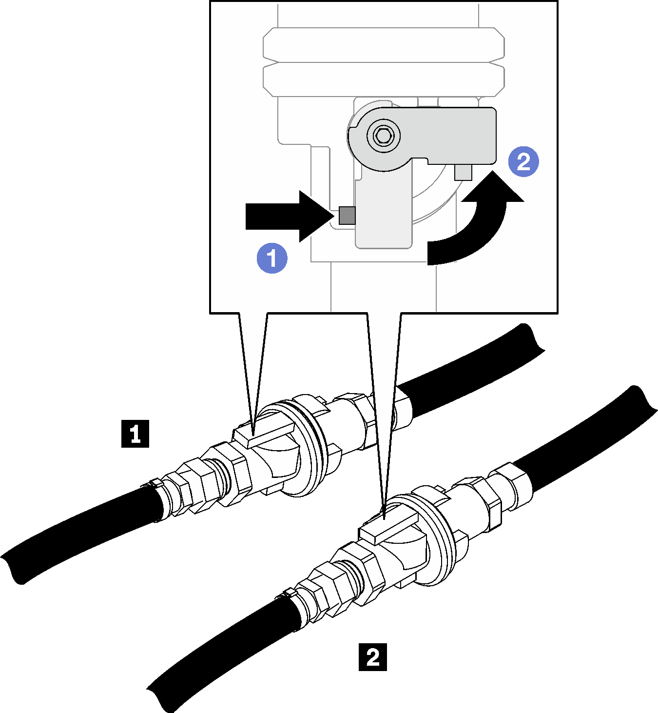
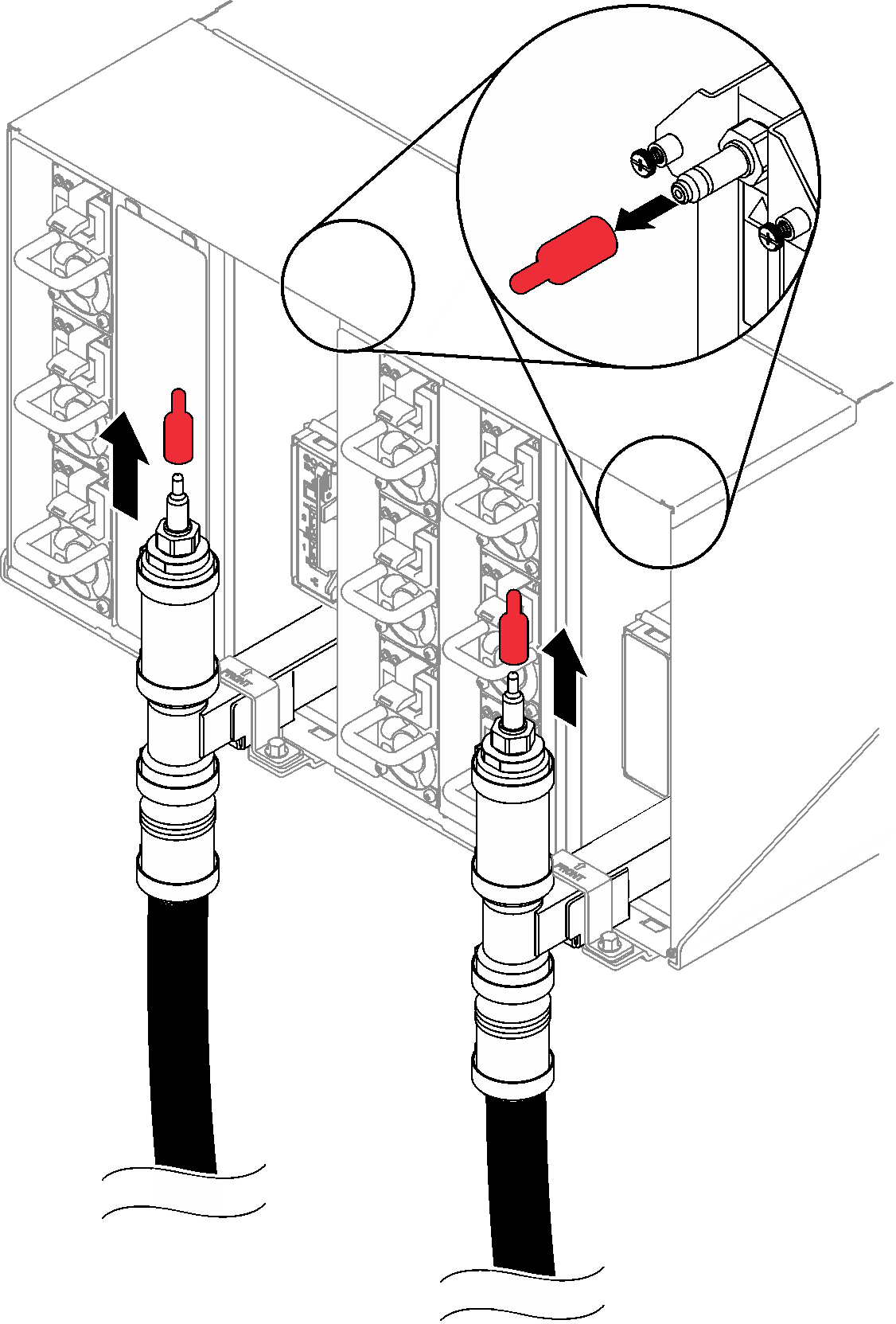
Table 1. Eaton ball valves 1 Rack supply 2 Rack return - Remove the red quick connect plug covers from the tops of each manifold, and on the rear of each manifold section.Figure 2. Quick connect plug covers removal
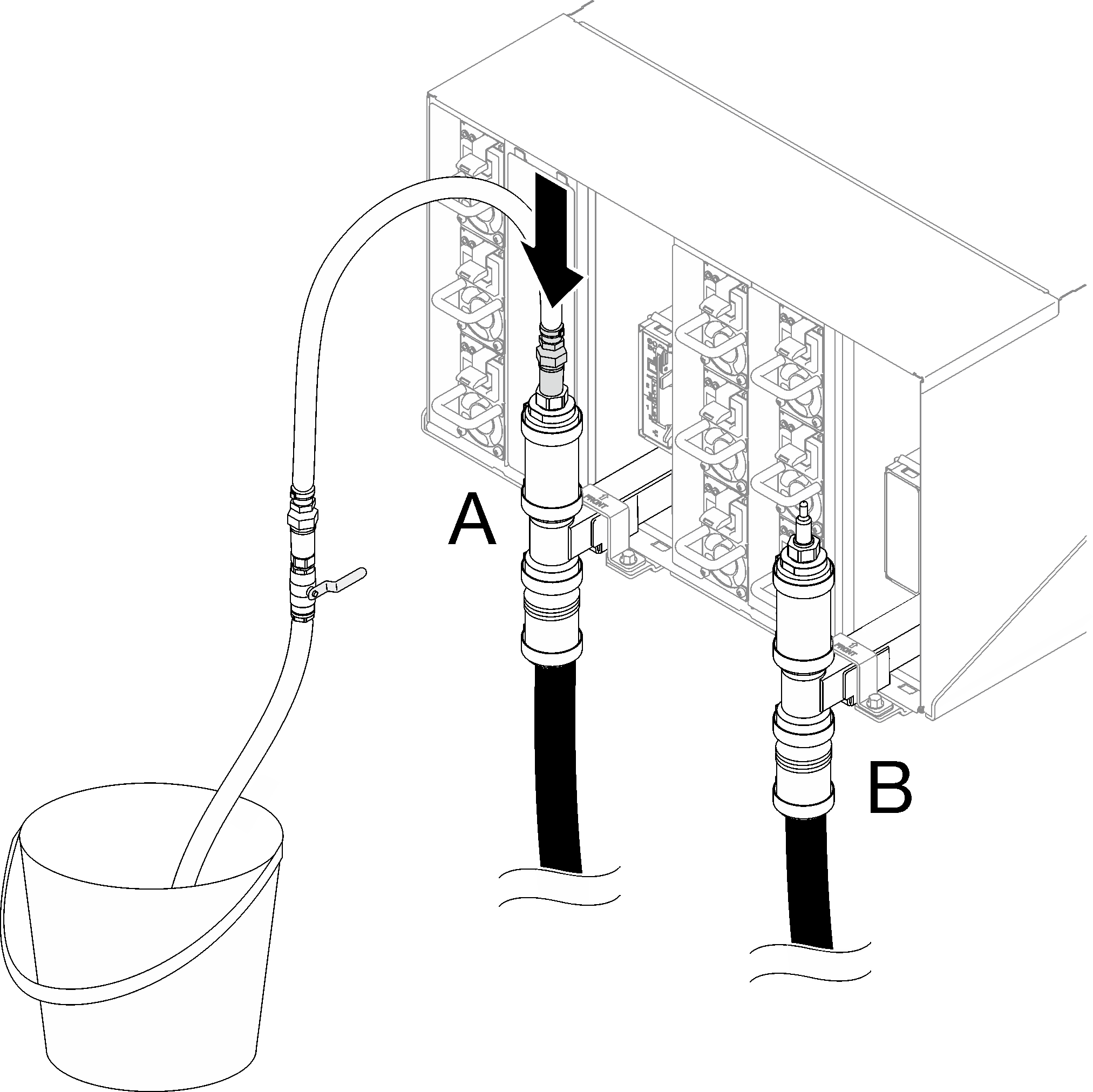
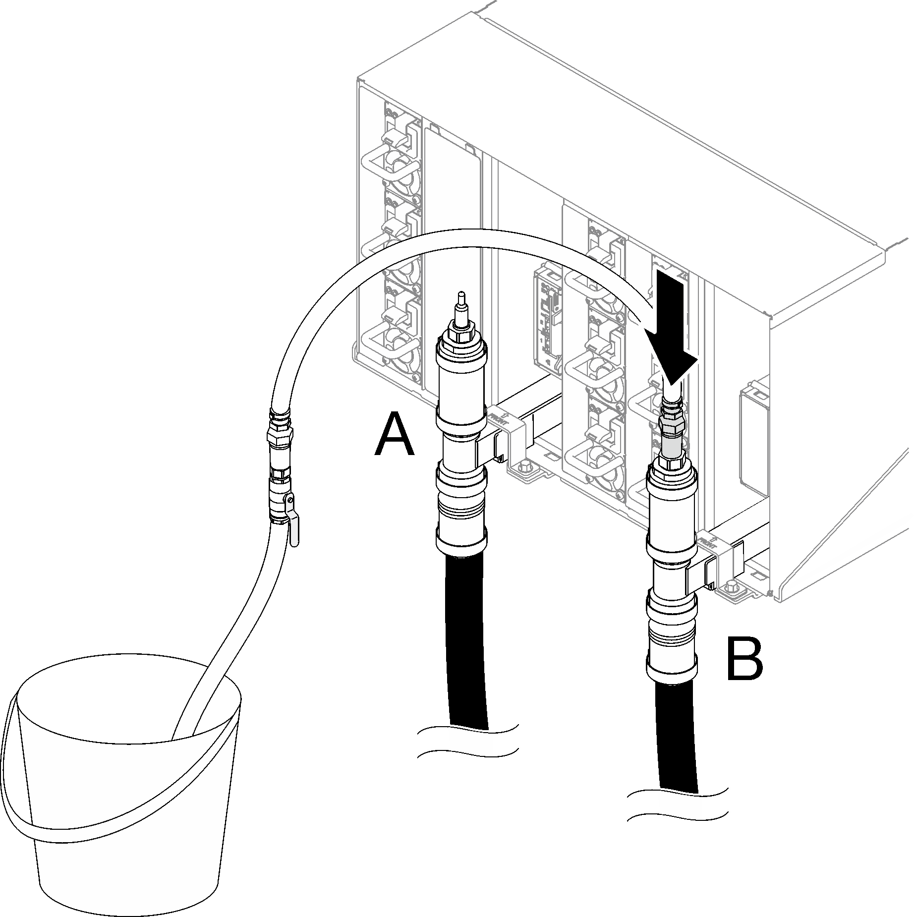
- Connect the hose assembly (supplied to customer installation site) to the top quick connect at Location A (top of the rack). Make sure the hose still remains in the bucket with the valve closed (valve handle perpendicular to the hose).Figure 3. Hose assembly to top quick connect
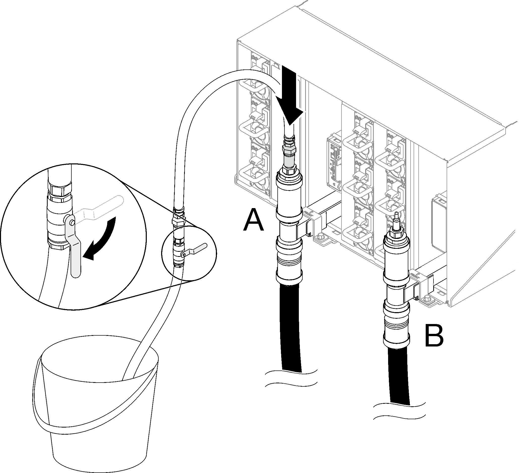
- Slowly open the hose valve to allow a steady stream of water to drain. Close the hose valve once water stops flowing (it may take approximately one minute).Figure 4. Hose assembly at Location A
- Disconnect the hose assembly from Location A and connect it to Location B. Slowly open the hose valve to allow a steady stream of water to drain. Close the hose valve once water stops flowing.Figure 5. Hose assembly at Location B
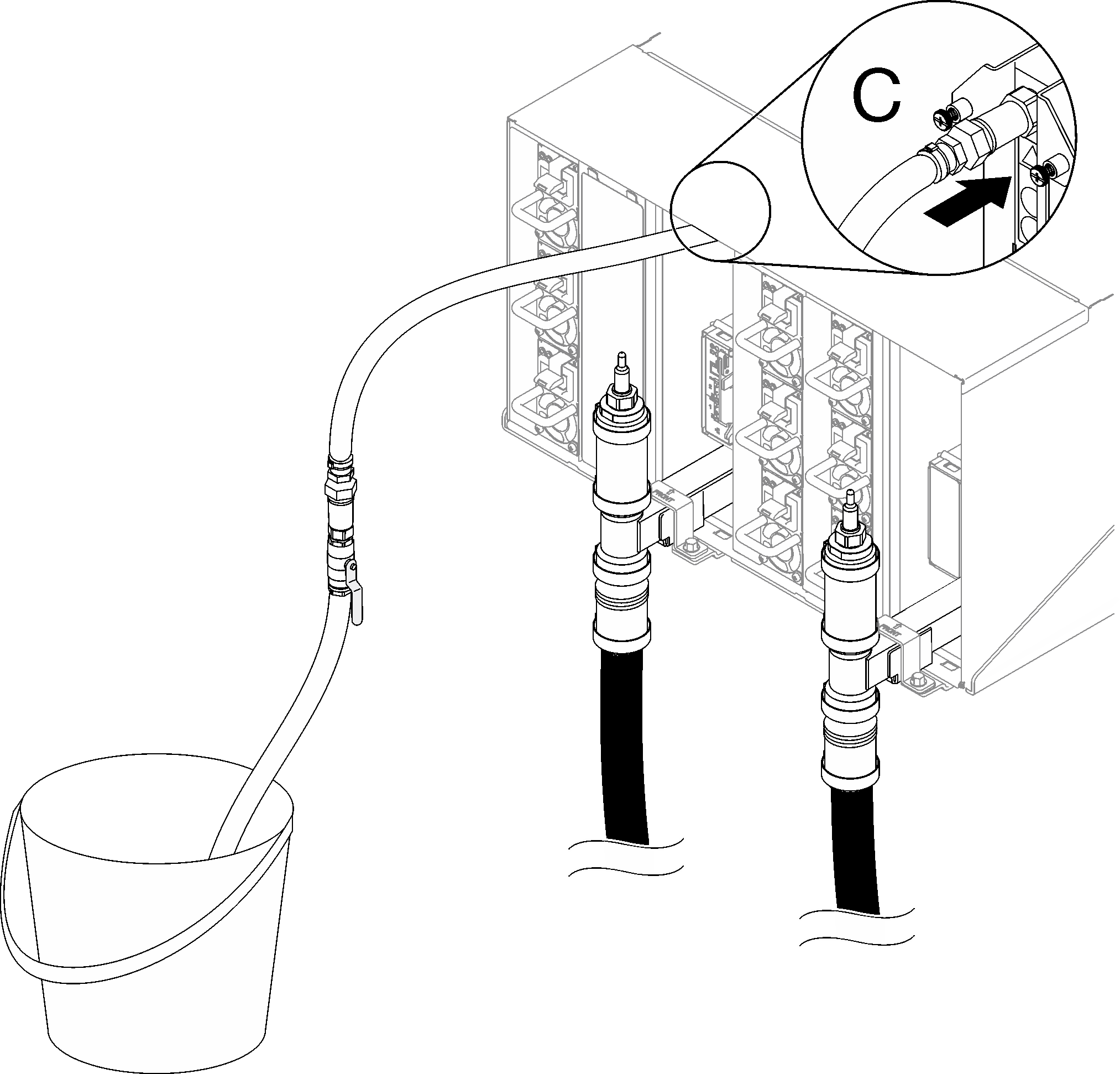
- Disconnect the hose assembly from Location B and connect it to Location C. Slowly open the hose valve to allow a steady stream of water to drain. Close the hose valve once water stops flowing.Figure 6. Hose assembly at Location C
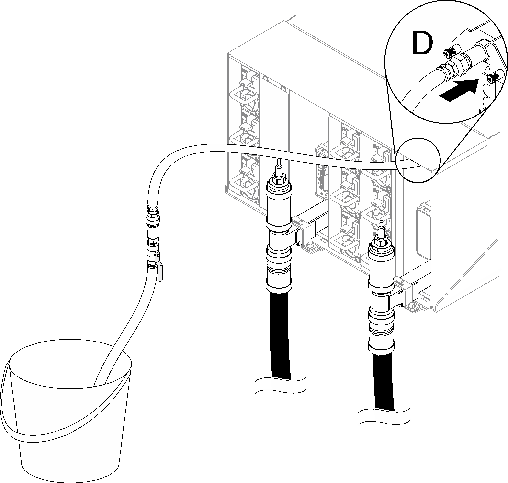
- Disconnect the hose assembly from Location C and connect it to Location D. Slowly open the hose valve to allow a steady stream of water to drain. Close the hose valve once water stops flowing.Figure 7. Hose assembly at Location D
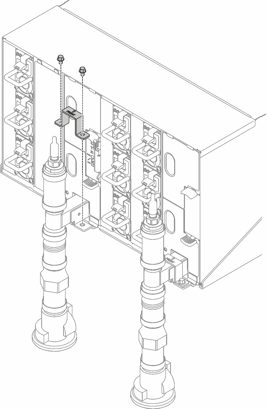
- Remove manifold retention bracket that is retaining the manifold (top enclosure position only).Figure 8. Retention bracket removal
- Remove the manifold.
 Remove four screws (using the screwdriver contained in the manifold repair kit) between manifold bracket and enclosure.
 Remove the manifold from the enclosure.
 Remove the drip sensor tray from the manifold.Figure 9. Manifold removal
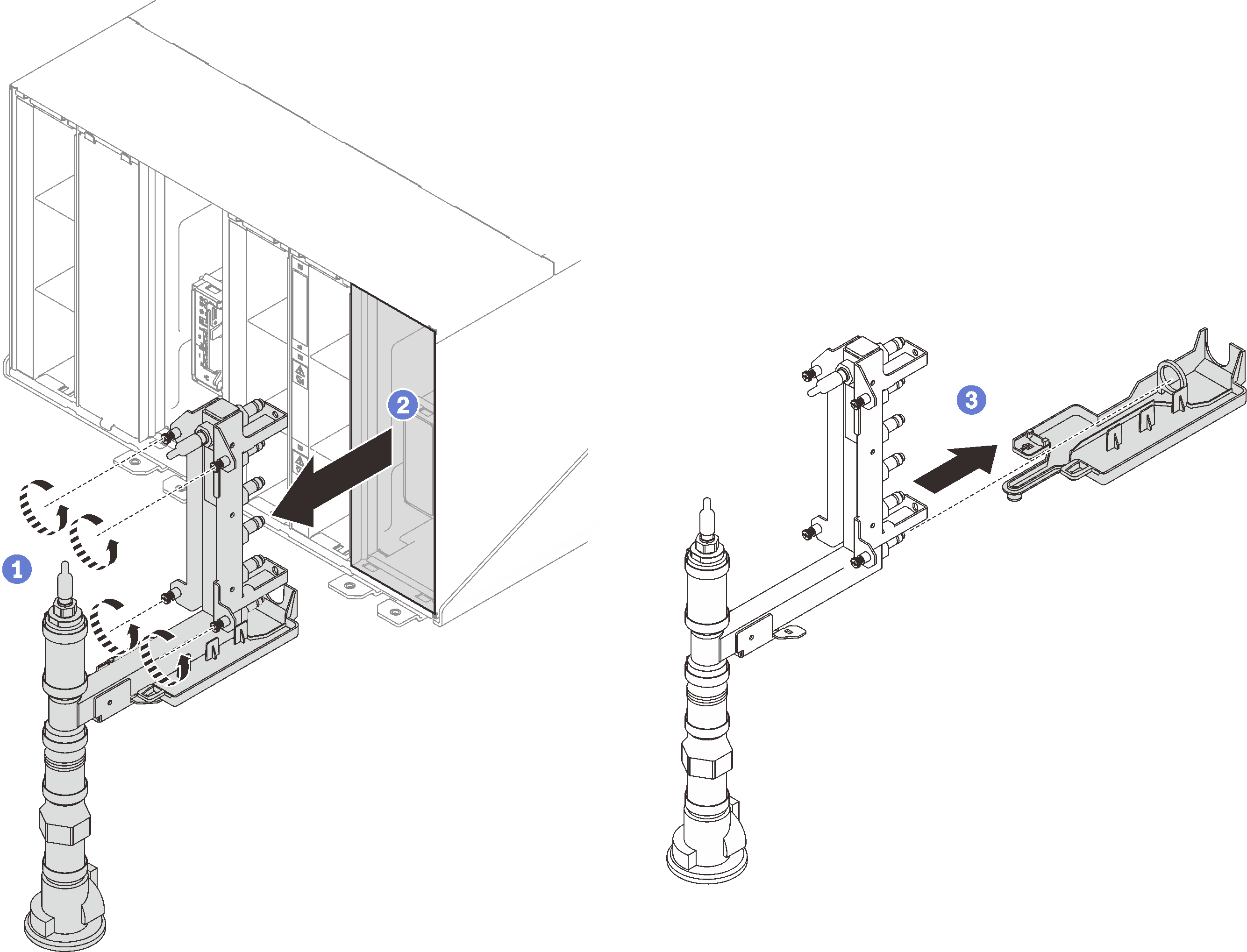 Figure 10. Manifold screw locations
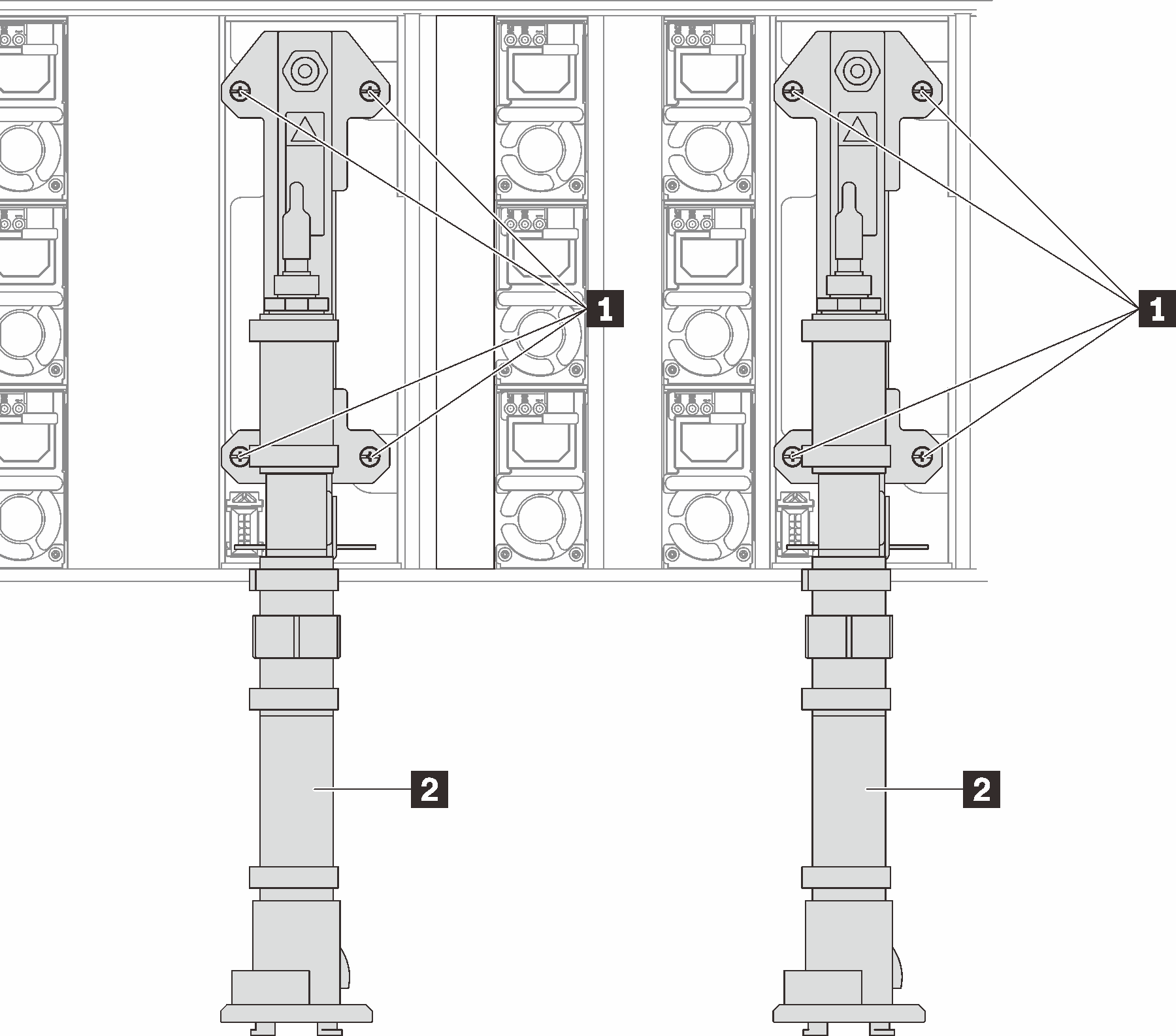
Table 2. Manifold screw locations 1 Screws 2 Manifold
- If you need to replace a manifold section.
- Place a pan under the manifold section that needs to be replaced.
- Use the 41 mm wrench supplied with the replacement manifold section kit to disconnect the couplings.
- Disconnect the manifold section that needs to be replaced.
Figure 11. Manifold disassemble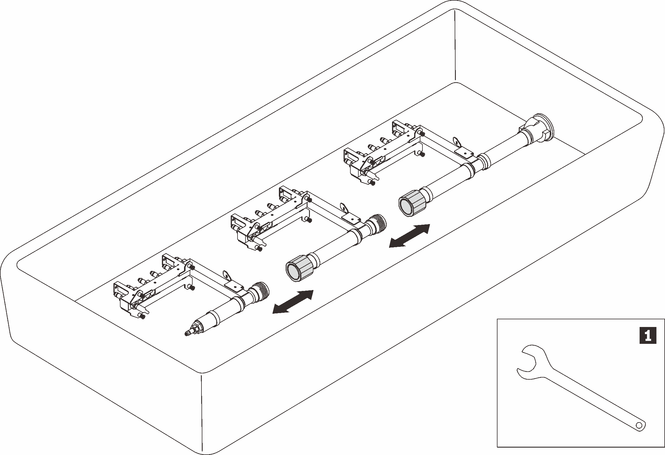
Table 3. Manifold disassemble 1 41 mm wrench
If you are instructed to return the component or optional device, follow all packaging instructions, and use any packaging materials for shipping that are supplied to you.