Remove the water loop
Use this information to remove the water loop.
Read the Installation Guidelines to ensure that you work safely.
Turn off the corresponding DWC tray that you are going to perform the task on.
Remove the tray (see Remove a DWC tray from the enclosure).
Remove the tray cover (see Remove the tray cover).
Remove both air baffles.
Figure 1. Air baffle removal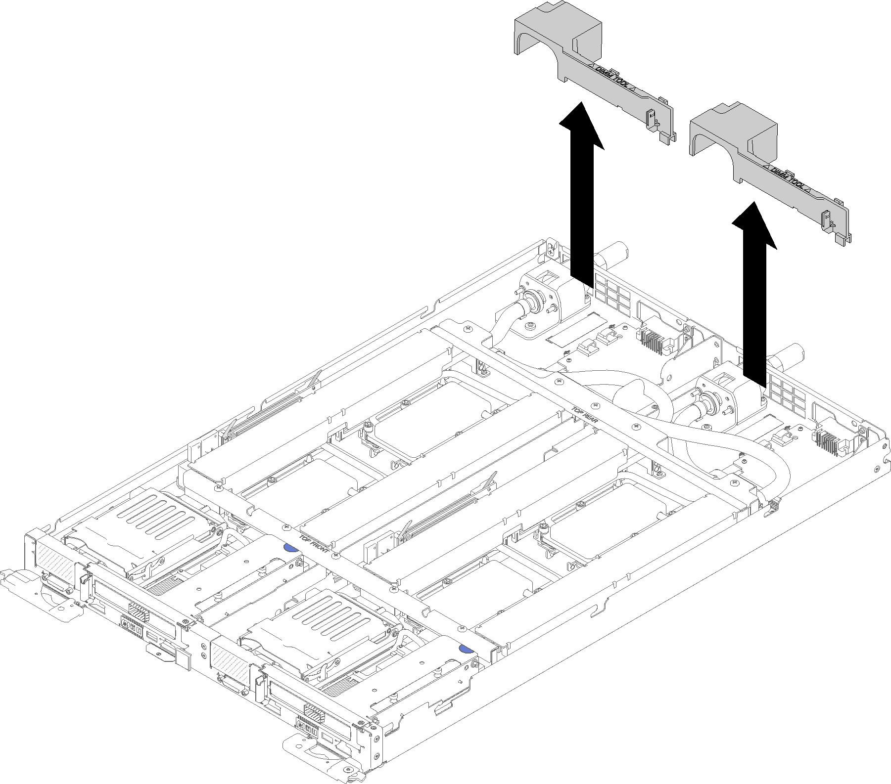
Remove the front and the rear cross braces (10x P2 screws).
Figure 2. Cross brace removal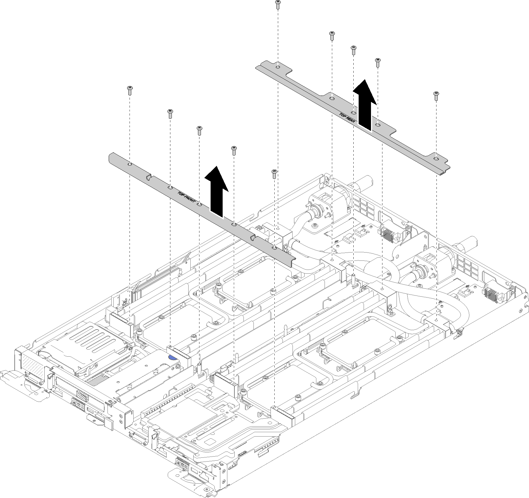
Remove all four DIMM covers and DIMMs for both nodes (see Remove a DIMM).
Remove M.2 Backplanes from both nodes (see Remove the M.2 backplane).
Remove drive cage assemblies from both nodes (see Remove a drive cage assembly).
Remove PCIe riser assemblies from both nodes if applicable (see Remove an adapter or Remove an Internal Faceplate Transition (IFT) adapter depending on your configuration).
Complete the following steps to remove the water loop.
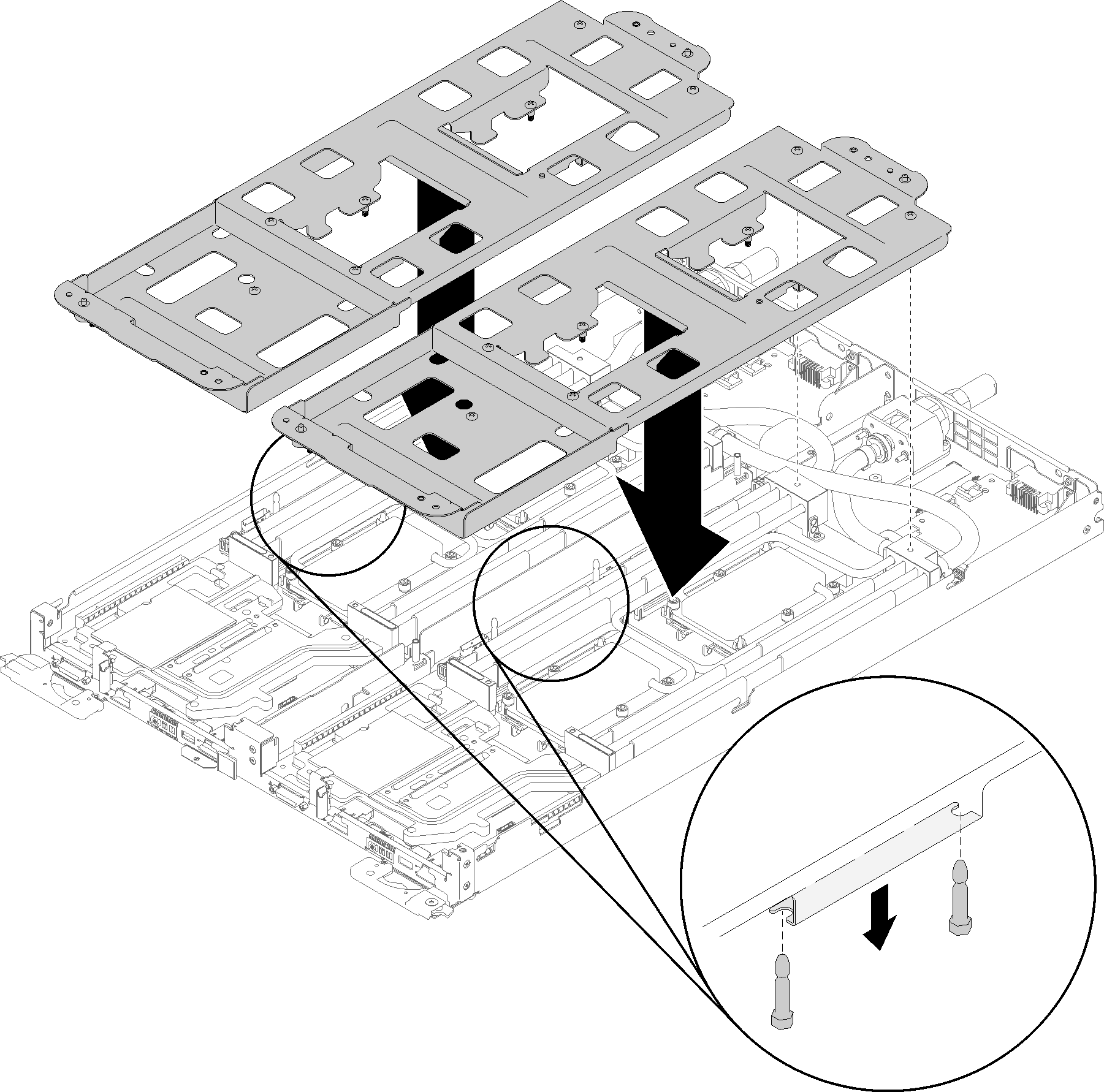
- Carefully place each water loop carrier down on the water loop one at a time and ensure they are seated firmly on the water loop.Figure 3. Water loop carrier installation
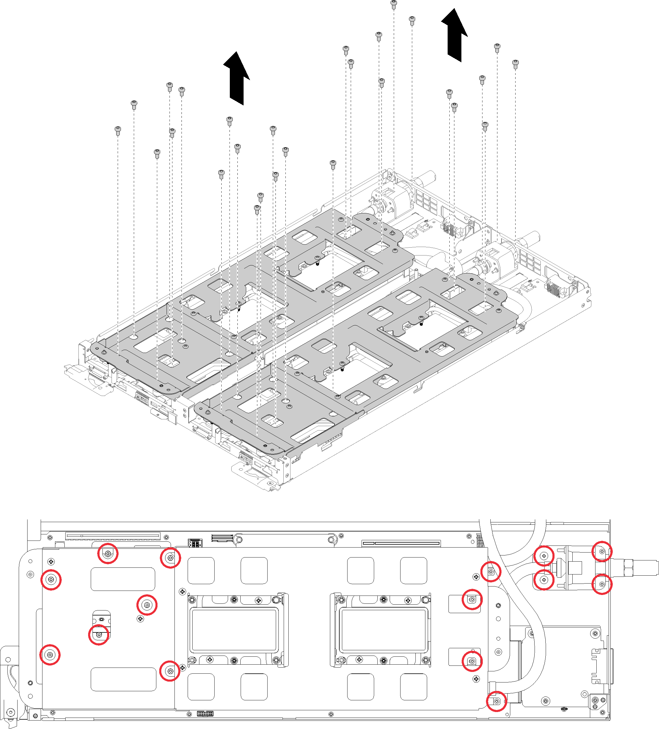
- Remove water loop screws (30x silver Torx T10 screws).NoteThe following illustration shows screw locations for one node. The screw locations are identical for two nodes.Figure 4. Silver T10 screw removal
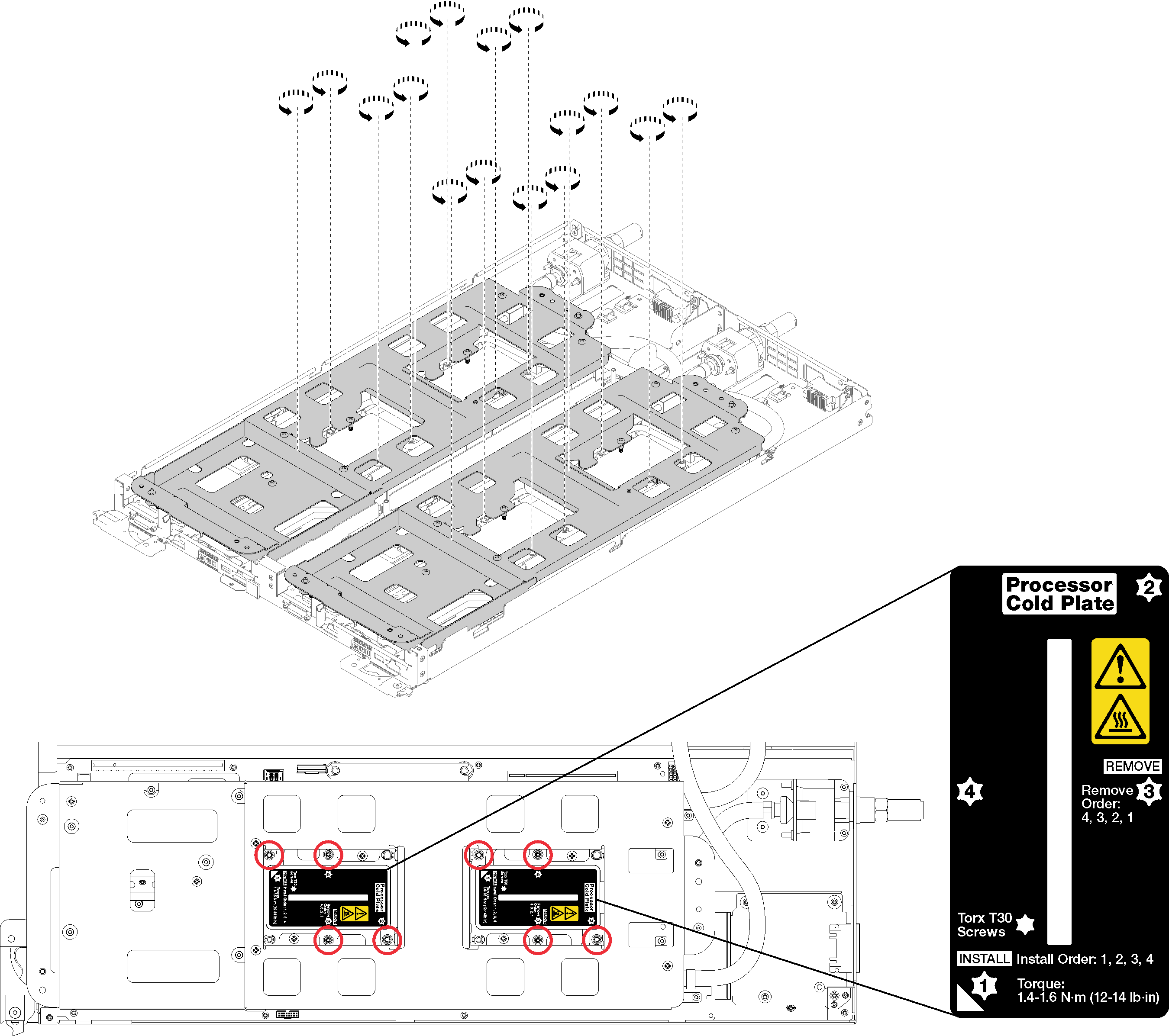
- Fully loosen all Torx T30 captive fasteners (entire water loop has 16 total Torx T30 captive fasteners) on cold plates in the removal sequence shown on the cold plate label.AttentionTo prevent damage to components, make sure that you follow the indicated loosening sequence.NoteThe following illustration shows screw locations for one node. The screw locations are identical for two nodes.Figure 5. Loosening Torx T30 captive fasteners
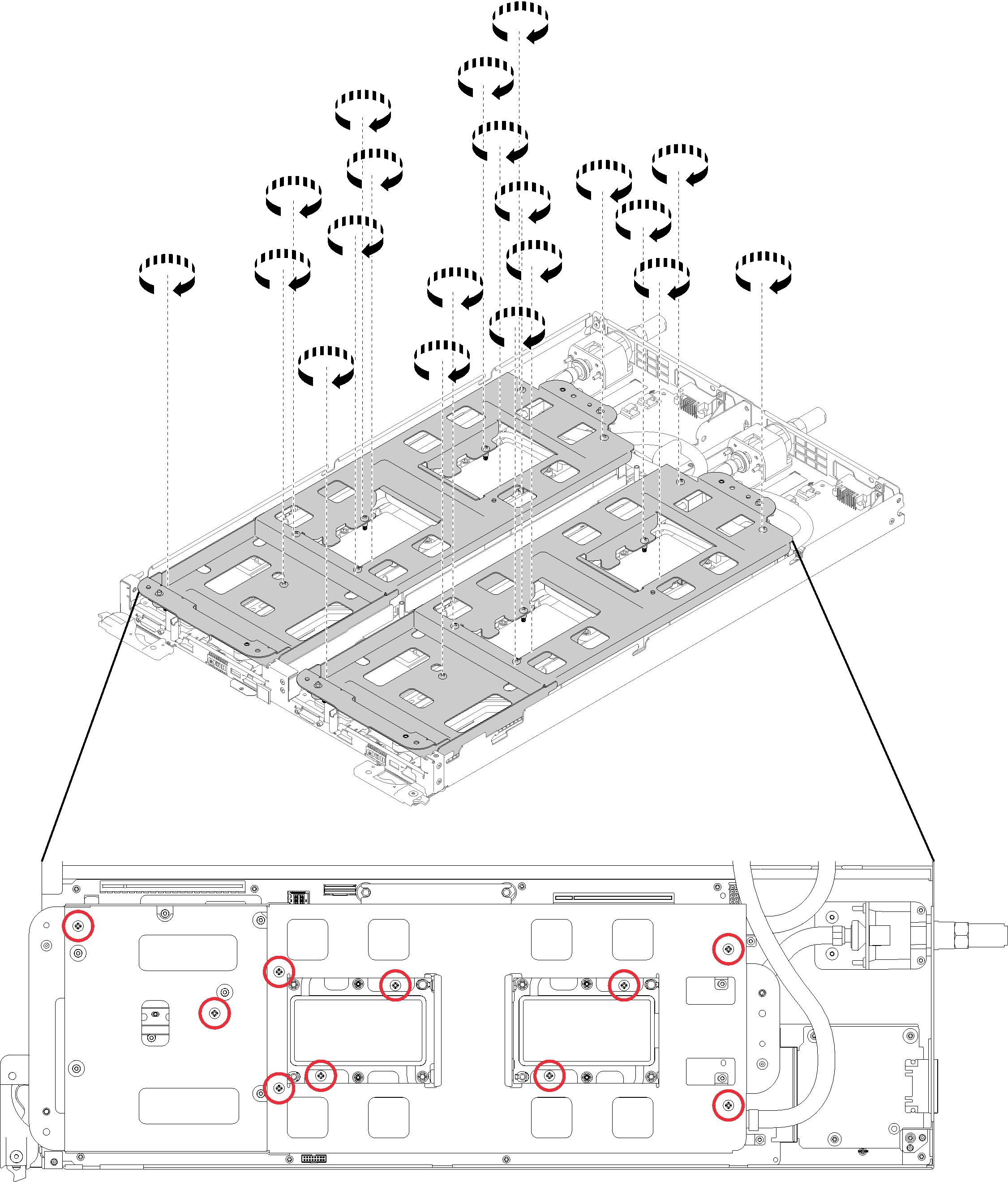
- Tighten captive water loop carrier screws (20x P2 screws) to secure the carrier to the water loop.NoteThe following illustration shows screw locations for one node. The screw locations are identical for two nodes.Figure 6. Tightening captive P2 screws
- Fold the water loop.
- Carefully lift the water loop up off the system board, then unhook the quick connect from the four alignment posts and slide the quick connect out of the opening in the rear of the tray.
- Carefully rotate the water loop so one half is sitting on top of the other half. There are dimples and openings at the ends of the water loop carriers that nest when two carriers are aligned back to back.
- Fasten two captive thumbscrews to secure water loop carriers to each other.
Figure 7. Water loop rotation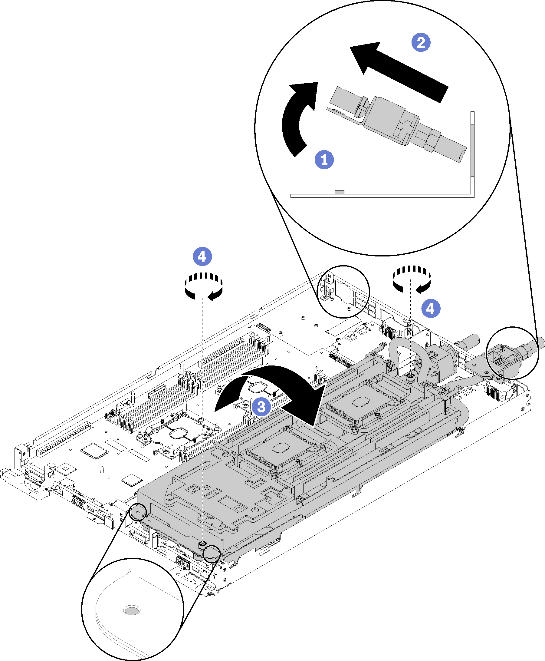
- Remove the water loop.
- Carefully lift the water loop up off the system board.
- Unhook the quick connect from the four alignment posts and slide the quick connect out of the opening in the rear of the tray.
- Lift the water loop out of the node.
Figure 8. Water loop removal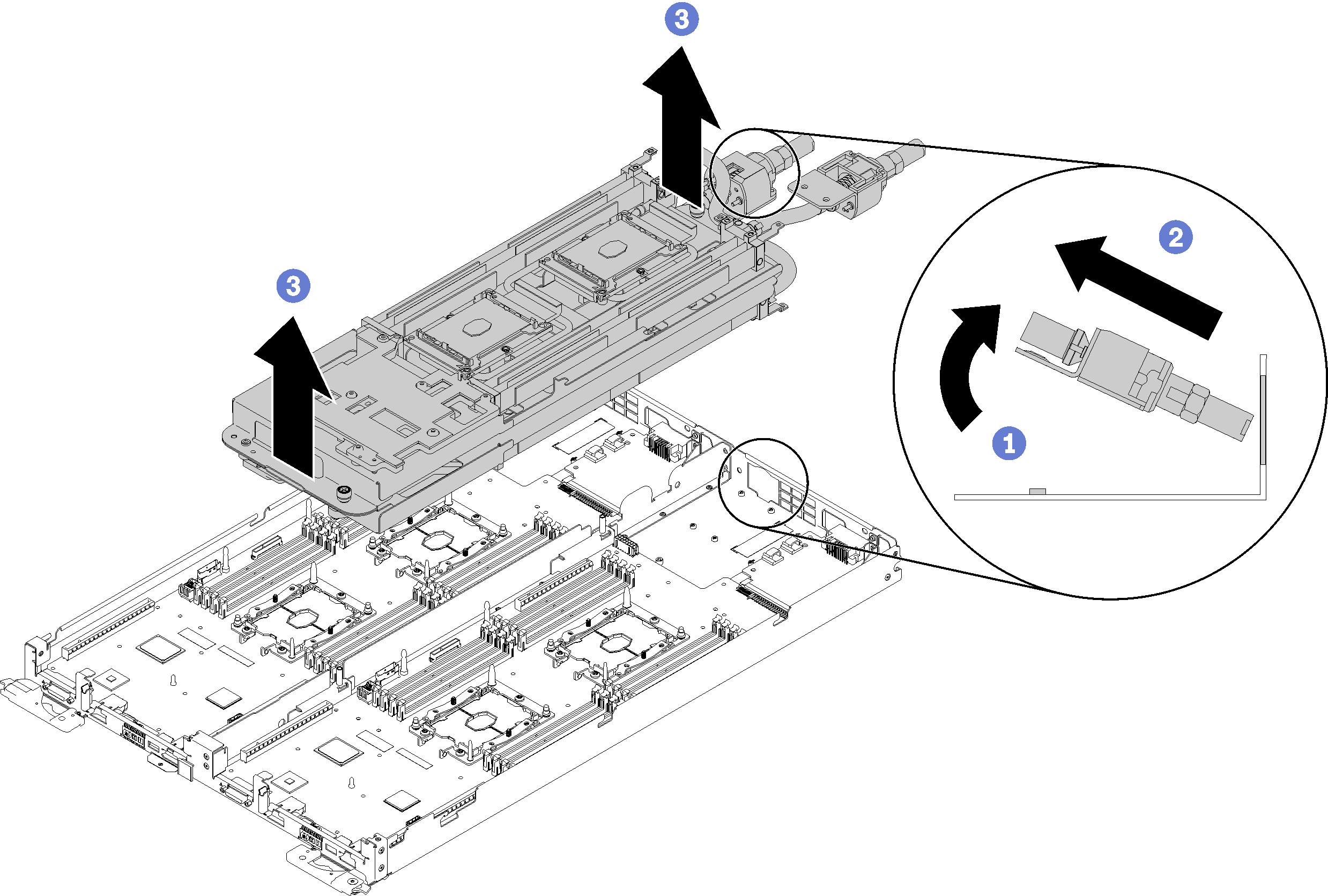
If you are instructed to return the component or optional device, follow all packaging instructions, and use any packaging materials for shipping that are supplied to you.
Demo video