System-board switches
The following illustration shows the location of the switches on the system board.
Note
If there is a clear protective sticker on the top of the switch blocks, remove and discard it to access the switches.
Figure 1. System-board switches
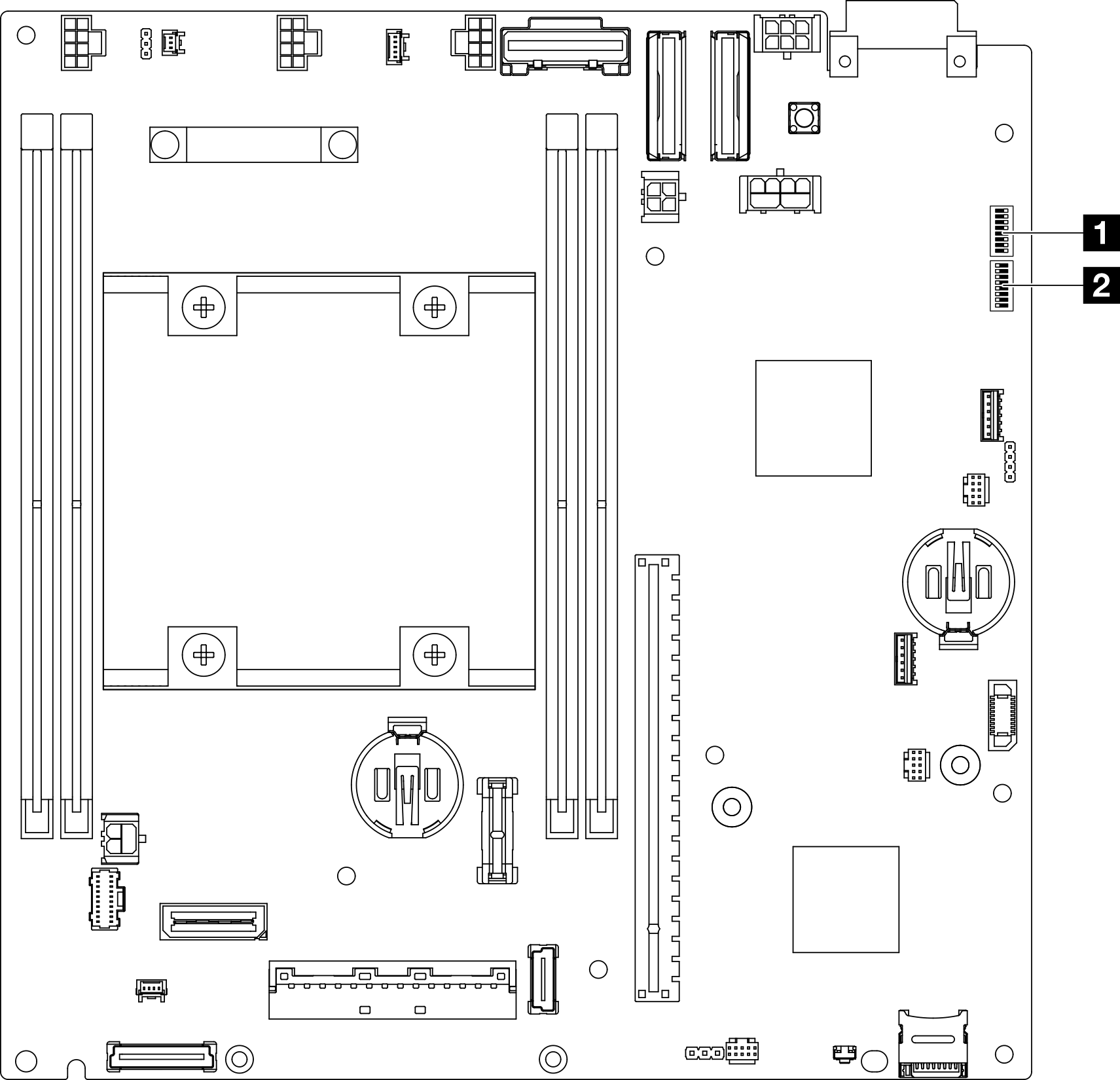
| 1 Switch block (SW22) | 2 Switch block (SW1) | 3 Switch block (SW18) |
Important
Before changing any switch settings or move any jumpers, turn off the server; then, disconnect all power cords and external cables. Review the following information:
- Any system-board switch or jumper block that is not shown in the illustrations in this document are reserved.
The following table describes the switches on the system board.
| Switches block | Switch number | Switch name | Usage description | |
|---|---|---|---|---|
| On | Off | |||
| SW1 | 1 | XCC boot backup | The node will boot by using a backup of the XCC firmware | Normal (default) |
| 2 | CMOS clear | Clears the real-time clock (RTC) registry | Normal (default) | |
| 3 | Password override | Overrides the power-on password | Normal (default) | |
| 4 | (Reserved) | (Reserved) | Normal (default) | |
| 5 | (Reserved) | (Reserved) | Normal (default) | |
| 6 | Machine Engine (ME) recovery override | ME boots to recovery | Normal (default) | |
| 7 | (Reserved) | (Reserved) | Normal (default) | |
| 8 | (Reserved) | (Reserved) | Normal (default) | |
| SW18 | 1 | ME firmware security override | Enables ME update mode | Normal (default) |
| 2 | XCC force update | Enables XCC force update | Normal (default) | |
| 3 | FPGA power permission override | Ignores Power Permission and allows system to power-on | Normal (default) | |
| 4 | Force XCC reset | Forces XCC to reset | Normal (default) | |
| 5 | Force XCC CPU reset | Forces XClarity Controller and CPU to reset | Normal (default) | |
| 6 | (Reserved) | (Reserved) | Normal (default) | |
| 7 | Force FPGA reset | Forces FPGA to reset | Normal (default) | |
| 8 | (Reserved) | (Reserved) | Normal (default) | |
| SW22 | 1 | Serial function selection | Accesses XCC via the serial console connector. | Normal (default) |
| 2 | (Reserved) | (Reserved) | Normal (default) | |
Give documentation feedback