Front view
This section contains information about the controls, LEDs, and connectors in the front of the server, including the front I/O modules.
Based on two types of drive assemblies and two types of I/O module boards, there are four possible configurations of ThinkEdge SE350 V2.
Server front views of different configurations
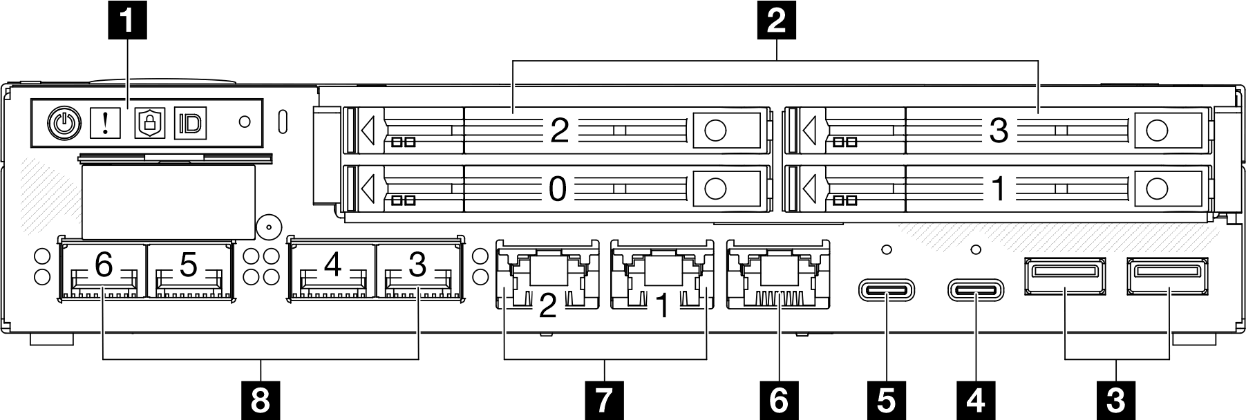
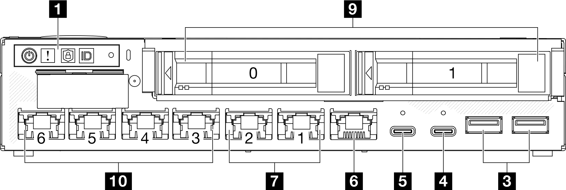
Above are the front views of
7mm drives with 10/25GbE I/O module; and
15mm drives with 1GbE I/O module.
- In addition, the other two configurations of ThinkEdge SE350 V2 include:
7mm drives with 1GbE I/O module; and
15mm drives with 10/25GbE I/O module.
| 1 Front operator panel buttons and LEDs | 6 XCC system management port (10/100/1000 Mbps RJ-45) |
| 2 7mm 2.5-inch drive bays (bays 0 to 3) | 7 2.5GbE RJ-45 connectors |
| 3 USB 3.2 Gen 1 Type-A connectors | 8 10/25GbE SFP28 connectors |
| 4 USB 3.2 Gen 1 Type-C connector (supporting display) | 9 15mm 2.5-inch drive bays (bays 0 to 1) |
| 5 USB 2.0 Gen 1 Type-C connector with Lenovo XClarity Controller (XCC) management | 10 1GbE RJ-45 connectors |
1 Front operator panel buttons and LEDs
For more information about the front operator panel buttons and LEDs, see Front operator panel LEDs.
When the security bezel is installed, the front operator panel and the USB Type-C connectors are not accessible.
When the shipping bracket is installed, the front operator panel is not accessible.
2 9 2.5-inch drive bays (bay 0 to 3)
Install 2.5-inch drives or drive bay fillers to these bays (see Install a hot-swap drive).
For more information about the drive LEDs, see Drive LEDs.
3 4 5 6 7 8 10 Front I/O Module
The following illustrations show the front I/O module of ThinkEdge SE350 V2.
Depending on the configuration, the front I/O module is determined by one of the following networking options:
10/25GbE I/O module
1GbE I/O module
For more information about LAN port LEDs, see LAN port LEDs.
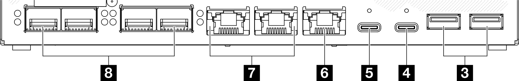
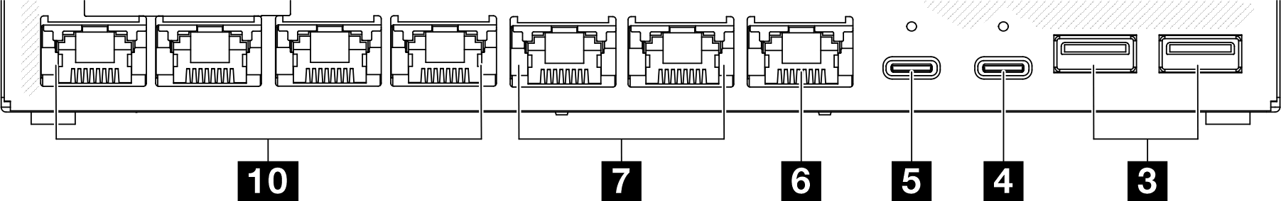
3 USB 3.2 Gen 1 Type-A connectors
There are two USB 3.2 Gen 1 Type-A connectors in the front of the server. These connectors are available for a device that requires USB 2.0 or 3.0 Type-A connection, such as a keyboard, a mouse, or a USB flash drive.
4 USB 3.2 Gen 1 Type-C connector (supporting display)
When the security bezel is installed, the front operator panel and the USB Type-C connectors are not accessible.
5 USB 2.0 Gen 1 Type-C connector with Lenovo XClarity Controller (XCC) management
When the security bezel is installed, the front operator panel and the USB Type-C connectors are not accessible.
Connection to Lenovo XClarity Controller is primarily intended for users with a mobile device running the Lenovo XClarity Controller mobile application. When a mobile device is connected to this USB port, an Ethernet over USB connection is established between the mobile application running on the device and the Lenovo XClarity Controller.
The following mode is supported:
BMC only mode
In this mode, the USB port is always solely connected to Lenovo XClarity Controller.
6 XCC system management port (10/100/1000 Mbps RJ-45)
The server has a 1 GbE RJ-45 connector dedicated to Lenovo XClarity Controller (XCC) functions. Use this connector to manage the server, by using a dedicated management network. If you use this connector, the Lenovo XClarity Controller cannot be accessed directly from the production network. A dedicated management network provides additional security by physically separating the management network traffic from the production network. You can use the Setup utility to configure the server to use a dedicated systems-management network or a shared network.
7 8 10 Ethernet connectors
7 2.5GbE RJ-45 connectors
8 10/25GbE SFP28 connectors
10 1GbE RJ-45 connectors
These ports are used to attach Ethernet cables for LANs. Each Ethernet connector has status LEDs to help identify the Ethernet connectivity and activity. For more information about these LEDs, see LAN port LEDs.
Install I/O fillers
Install the I/O fillers when the connectors are not in use. The connectors could be damaged without proper protection of the fillers.
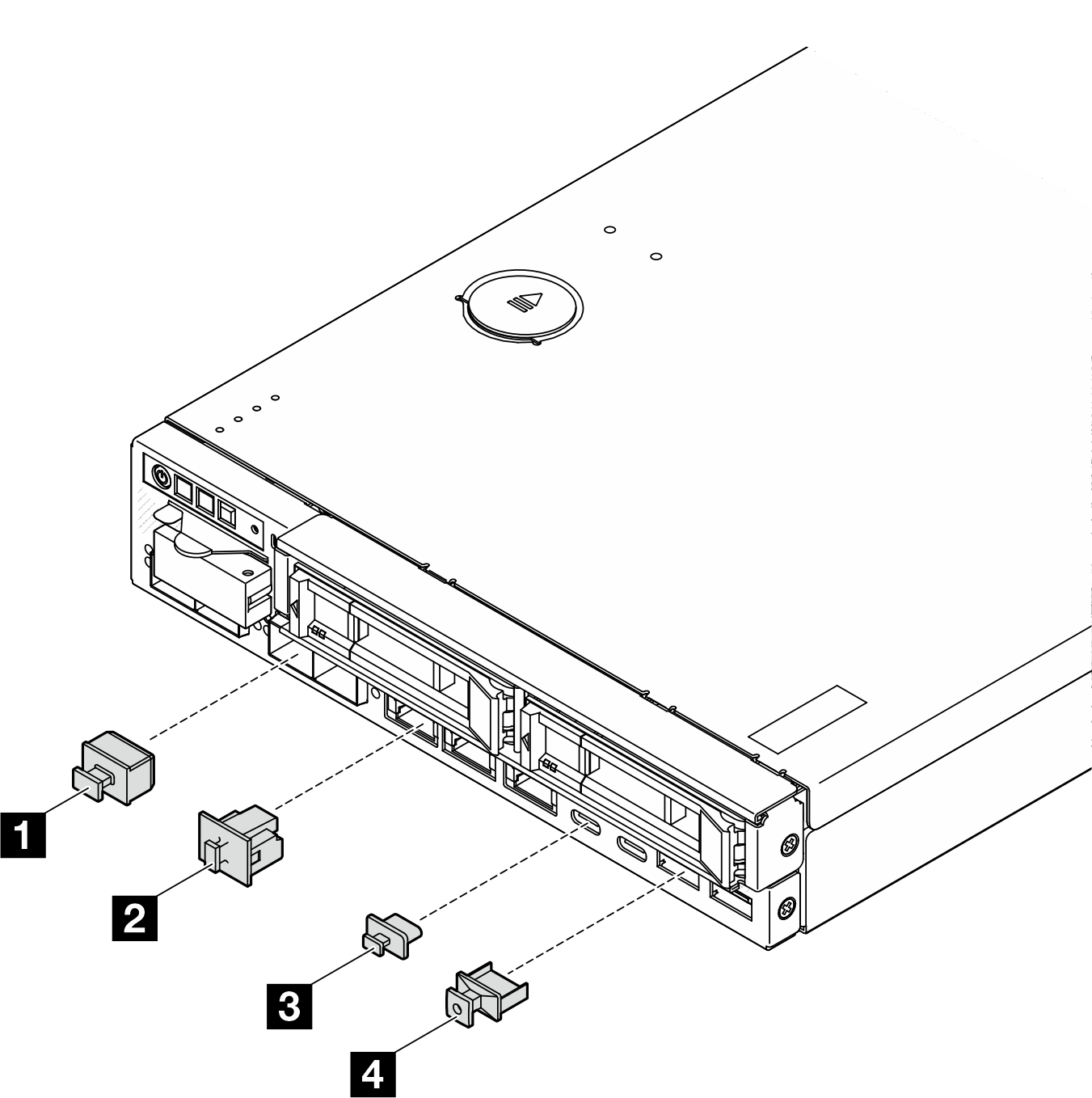
| 1 SFP+ filler (x4, if applicable for the server configuration) | 3 USB Type-A filler (x2) |
| 2 RJ-45 filler (x7 or x3, depending on the server configuration) | 4 USB Type-C filler (x2) |