Front operator panel
The front operation information panel of the server provides controls, connectors, and LEDs. The front operator panel varies by model.
Figure 1. Front operator panel
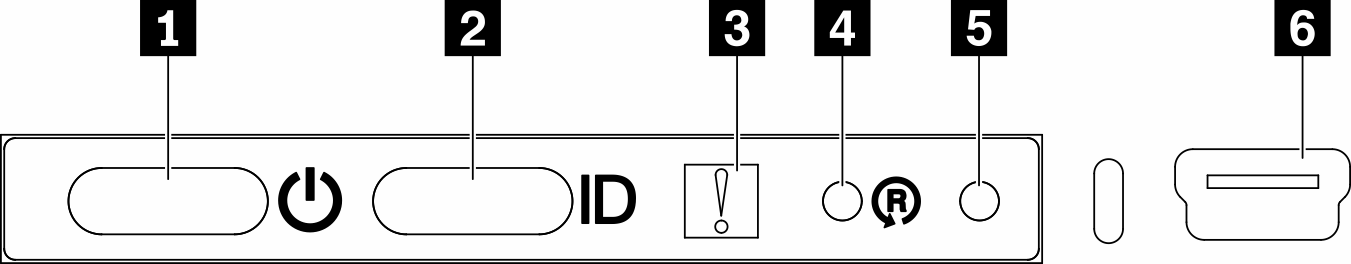
| 1 Power button/LED (green) | 4 Wireless enabled LOM package reset button |
| 2 Identification button/LED (blue) | 5 NMI button |
| 3 System-error LED (yellow) | 6 XClarity Controller mini USB connector |
1 Power button/LED (green): Press this button to turn the server on and off manually. The states of the power LED are as follows:
- Off: Power is not present or the power adapter, or the LED itself has failed.
- Flashing rapidly (4 times per second): The server is turned off and is not ready to be turned on. The power button is disabled. This will last approximately 5 to 10 seconds.
- Flashing slowly (once per second): The server is turned off and is ready to be turned on. You can press the power button to turn on the server.
- On: The server is turned on.
2 Identification button/LED (blue): Use this blue LED to visually locate the server among other servers. This LED is also used as a presence detection button. You can use Lenovo XClarity Administrator to light this LED remotely. The states of the identification LED are as follows:
- Off: Presence detection off.
- Flashing rapidly (4 times per second): (on XCC firmware version 3.10 or later) The server is not activated yet and has no power permission. See Activation guide to activate the system.
- Flashing slowly (once per second): Presence detection on.
- On: Presence detection on.
3 System-error LED (yellow): When this yellow LED is lit, it indicates that a system error has occurred.
4 Wireless enabled LOM module reset button: The reset pin for the wireless enabled LOM module.
5 NMI button: Press this button to force a nonmaskable interrupt (NMI) to the processor. By this way, you can blue screen the server and take a memory dump. You might have to use a pen or the end of a straightened paper clip to press the button.
6 XClarity Controller mini USB connector: Used to attach a mini USB to manage the system using XClarity Controller.
Give documentation feedback