System-board switches and jumpers
The following illustrations show the location of the switches and jumpers on the server.
Note
If there is a clear protective sticker on the top of the switch blocks, you must remove and discard it to access the switches.
Figure 1. System-board switches
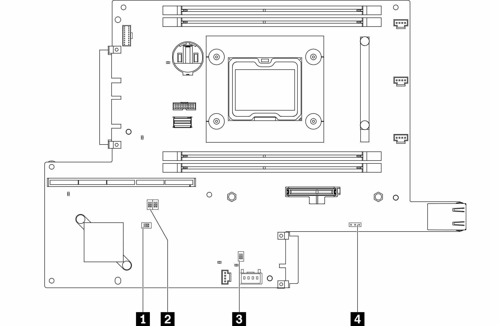
The following table describes the switches on the system board.
| Switches block | Switch number | Switch name | Usage description | |
|---|---|---|---|---|
| On | off | |||
| 1 SW2 | 1 | Machine Engine (ME) firmware security override | ME update mode | Normal (default) |
| 2 | N/A | Accessed by technician only | Normal (default) | |
| 2 SW8 | 1 | Password override | Overrides the power-on password | Normal (default) |
| 2 | XClarity Controller force update | Enables XClarity Controller force update | Normal (default) | |
| 3 | XClarity Controller boot backup | The node will boot by using a backup of the XClarity Controller firmware | Normal (default) | |
| 4 | Low security | Enable low security | Normal (default) | |
| 3 SW1 | 1 | TPM physical presence | Indicates a physical presence to the system TPM | Normal (default) |
| 2 | CMOS clear | Clears the real-time clock (RTC) registry | Normal (default) | |
The following table describes the jumper on the system board.
| Jumper name | Jumper setting |
|---|---|
| 4 Serial select jumper |
|
Important
- Before you change any switch settings or move any jumpers, turn off the server; then, disconnect all power cords and external cables. Review the information in Safety Information page, Installation Guidelines, Handling static-sensitive devices, and Power off the server.
- Any system-board switch or jumper block that is not shown in the illustrations in this document are reserved.
Give documentation feedback