System-board connectors
The following illustrations show the connectors on the system board.
Figure 1. System-board connectors
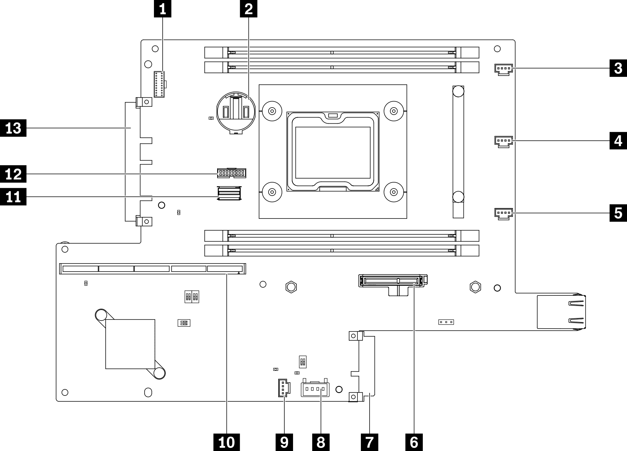
| 1 Front operator panel connector | 8 Lock switch connector |
| 2 3V Battery (CR2032) | 9 Intrusion switch connector |
| 3 Fan 1 connector | 10 Riser connector |
| 4 Fan 2 connector | 11 SATA Cable connector |
| 5 Fan 3 connector | 12 TPM connector |
| 6 M.2 boot adapter connector | 13 LOM module connector |
| 7 Power distribution module connector |
Give documentation feedback