Install the lock position switch with cable
Follow instructions in this section to install the lock position switch with cable.
About this task
S002
CAUTION
The power-control button on the device and the power switch on the power supply do not turn off the electrical current supplied to the device. The device also might have more than one power cord. To remove all electrical current from the device, ensure that all power cords are disconnected from the power source.
Attention
Read Installation Guidelines and Safety inspection checklist to ensure that you work safely.
Procedure
- Install the lock position switch with cable.
 Route the cable through the hole on the chassis.
 Fold the cable as shown; then, lower the lock position switch into the chassis, and push the switch toward the chassis wall. Make sure that the screw hole on the bracket aligns with the screw hole on the chassis.
 Secure the lock position switch with one screw.
Figure 1. Installing the lock position switch with cable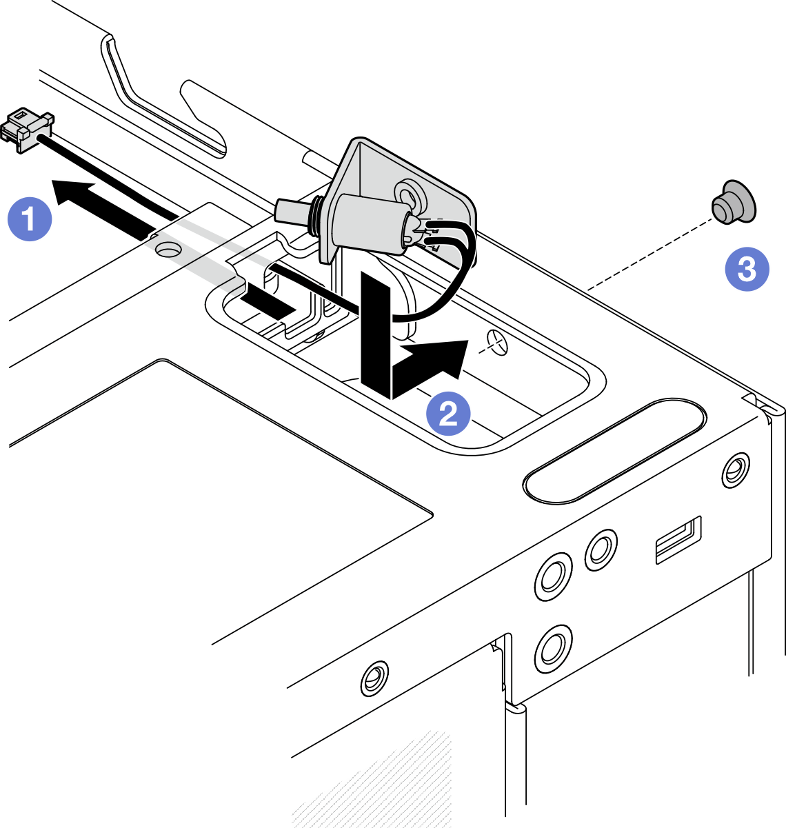
- Pull up the Mylar film, and connect the lock position switch cable to the I/O module board; then, stick the Mylar film back to the node, and make sure that the lock position switch cable is routed between the Mylar film and the chassis as shown.Figure 2. Lock position switch cable routing

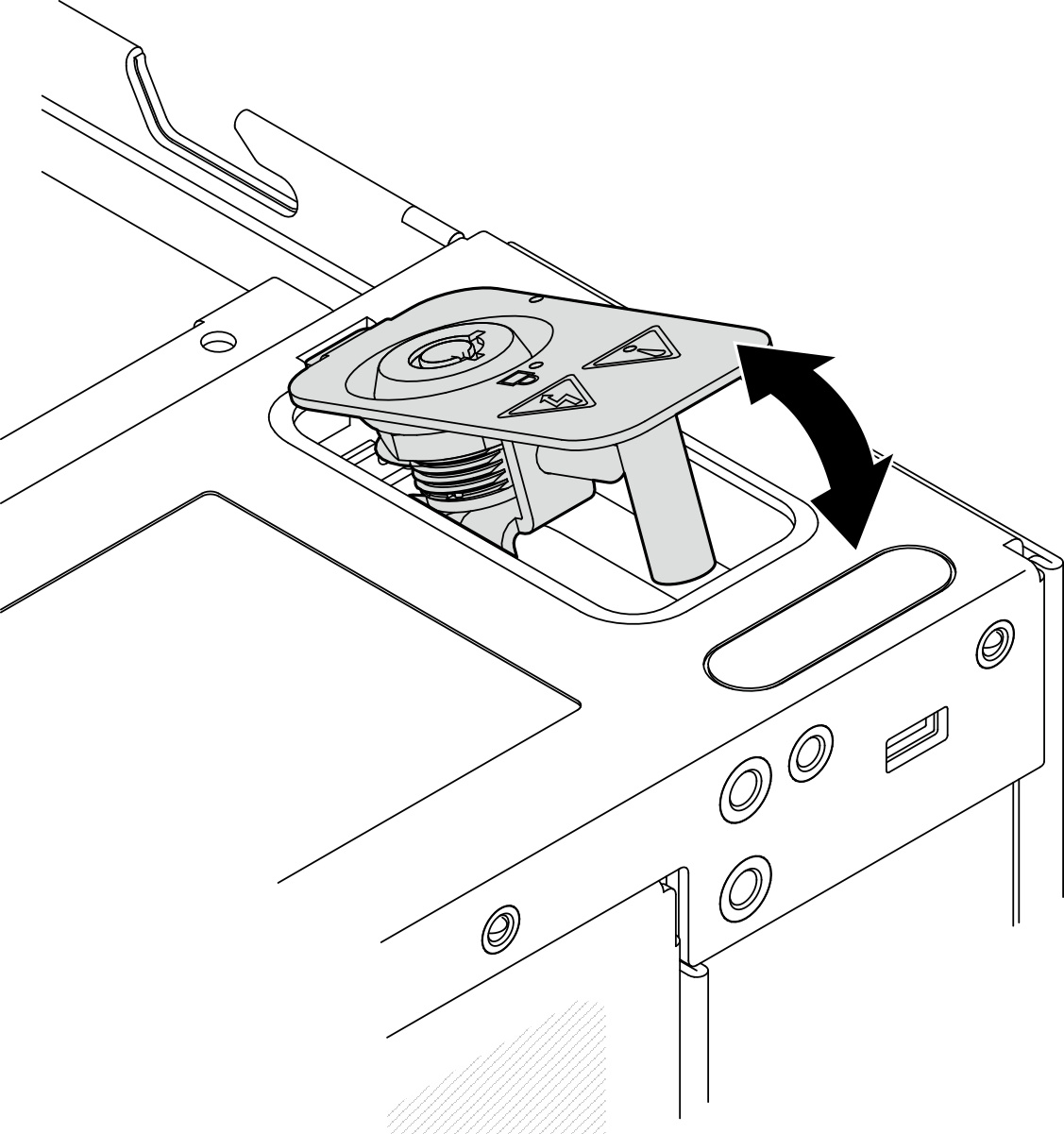
1 Lock position switch connector on the I/O module board - Insert the tab of the keylock bracket into the slot on the chassis; then, lower the keylock bracket down until it is seated in place.Figure 3. Installing the system security keylock
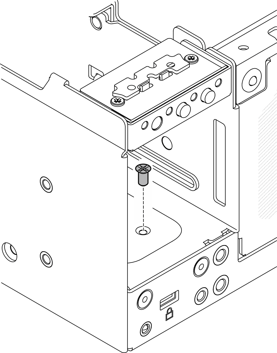
- Secure the system security keylock with one screwFigure 4. Fastening the screw
After this task is completed
Complete the parts replacement. See Complete the parts replacement.
Demo Video
Give documentation feedback