Remove the lock position switch with cable
Follow instructions in this section to remove the lock position switch with cable.
About this task
S002
CAUTION
The power-control button on the device and the power switch on the power supply do not turn off the electrical current supplied to the device. The device also might have more than one power cord. To remove all electrical current from the device, ensure that all power cords are disconnected from the power source.
Attention
Read Installation Guidelines and Safety inspection checklist to ensure that you work safely.
Power off the server and peripheral devices and disconnect the power cords and all external cables. See Power off the server.
If the node is installed in an enclosure or mounted, remove the node from the enclosure or mount. See Configuration guide.
Procedure
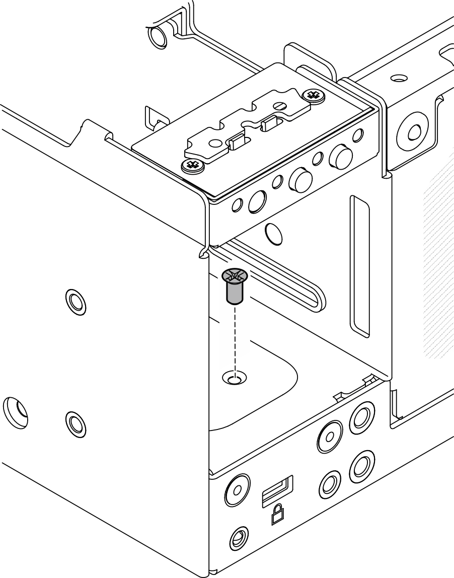
- Loosen the screw that secures the system security keylock.NoteIf necessary, disconnect the cable from the rear operator panel for easier operation.Figure 1. Loosening the screw
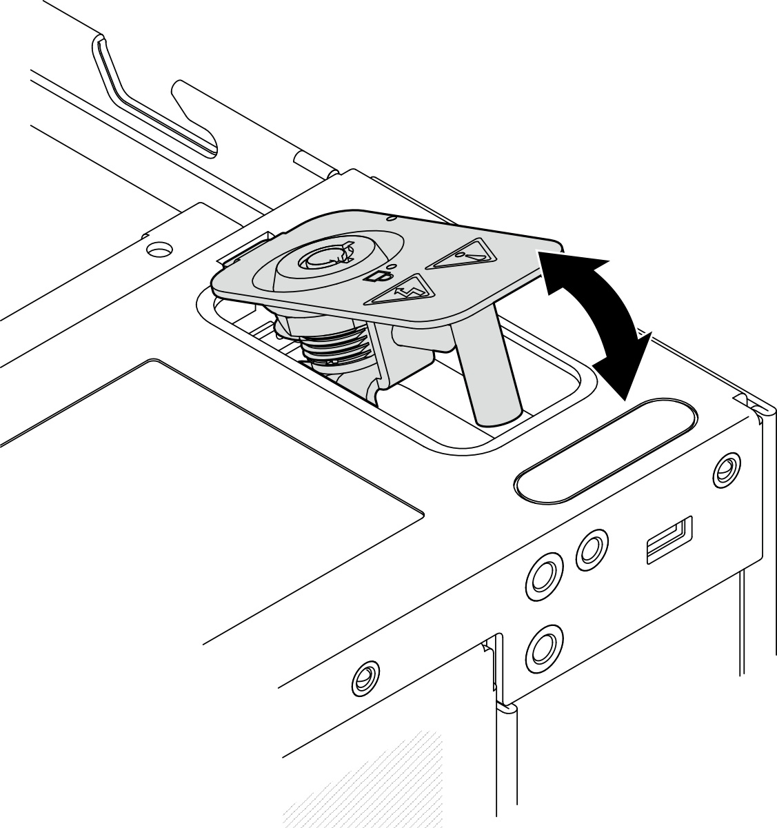
- Pinch the edge of the keylock bracket; then, lift the bracket and remove the system security keylock from the chassis.Figure 2. Removing the system security keylock
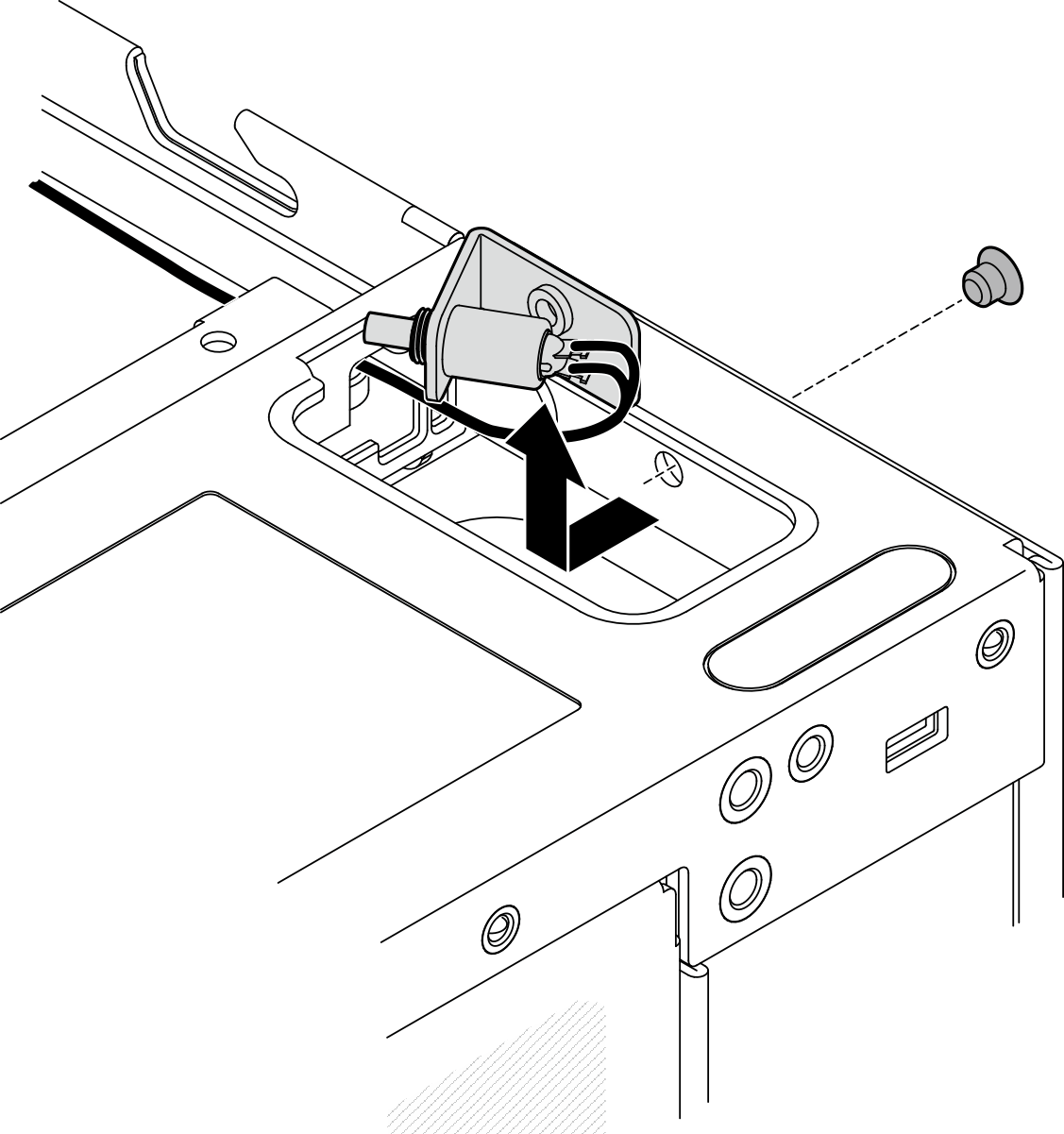
- Disconnect the lock position switch cable from the I/O module board.Figure 3. Lock position switch cable routing

1 Lock position switch connector on the I/O module board - Loosen the screw that secures the lock position switch; then, remove the switch from the chassis.Figure 4. Removing the lock position switch with cable
After this task is completed
Install a replacement unit. See Install the lock position switch with cable.
If you are instructed to return the component or optional device, follow all packaging instructions, and use any packaging materials for shipping that are supplied to you.
Demo Video
Give documentation feedback