Remove the internal power supply unit (AC PMB)
Follow instructions in this section to remove the internal power supply unit (AC PMB).
About this task

To avoid a shock hazard:
- Connect all power cords to a properly wired and grounded electrical outlet/source.
- Connect any equipment that will be attached to this product to properly wired outlets/sources.
- When possible, use one hand only to connect or disconnect signal cables.
- Never turn on any equipment when there is evidence of fire, water, or structural damage.
- The device might have more than one power cord, to remove all electrical current from the device, ensure that all power cords are disconnected from the power source.

Hazardous energy present. Voltages with hazardous energy might cause heating when shorted with metal, which might result in spattered metal, burns, or both.
Read Installation Guidelines and Safety inspection checklist to ensure that you work safely.
Power off the server and peripheral devices and disconnect the power cords and all external cables. See Power off the server.
If the node is installed in an enclosure or mounted, remove the node from the enclosure or mount. See Configuration guide.
Procedure
- Make preparation for this task.
- To ensure sufficient space for this task, place the signal cable that connects the front operator panel and rear operator panel outside of the chassis.Figure 1. Placing the signal cable
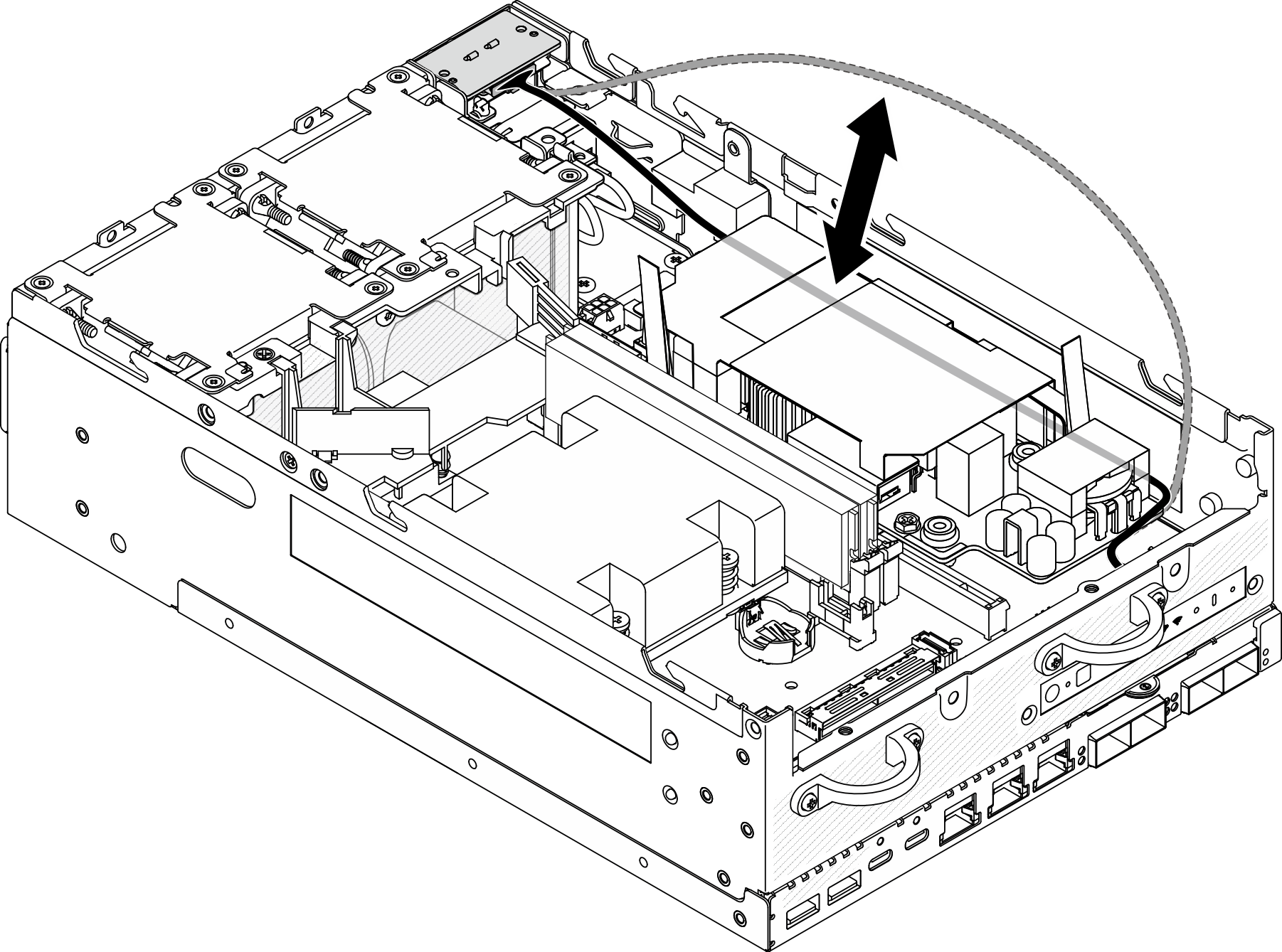
- To ensure sufficient space for this task, place the signal cable that connects the front operator panel and rear operator panel outside of the chassis.
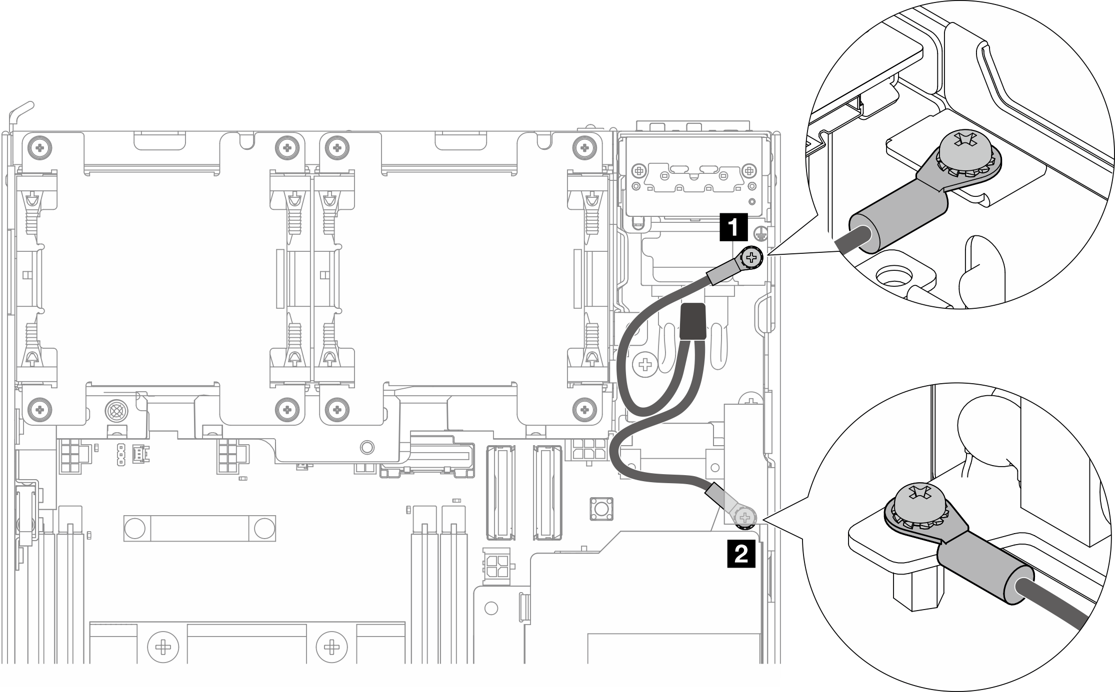
- Loosen the screws that secure the two grounding cables to disconnect the cables from 1 chassis and 2 internal power supply unit.Figure 2. Disconnecting the grounding cables
- Disconnect the power cable and PMB LED cable rom the internal power supply unit.
 Press and hold the power cable latch.
 Disconnect the power cable from the internal power supply unit.
 Disconnect the PMB LED cable from the internal power supply unit.
Figure 3. Disconnecting the cables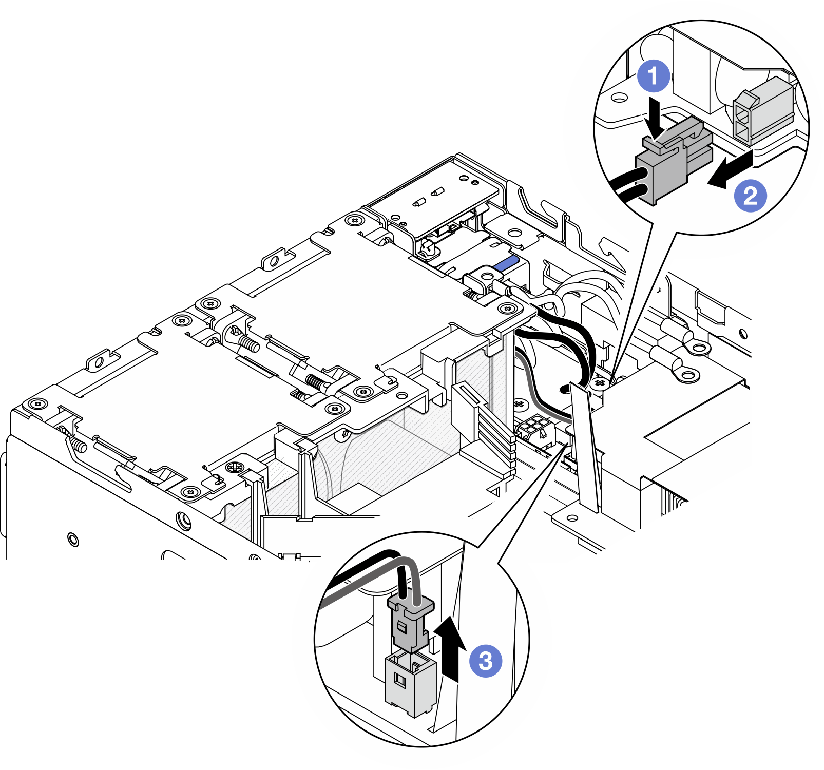
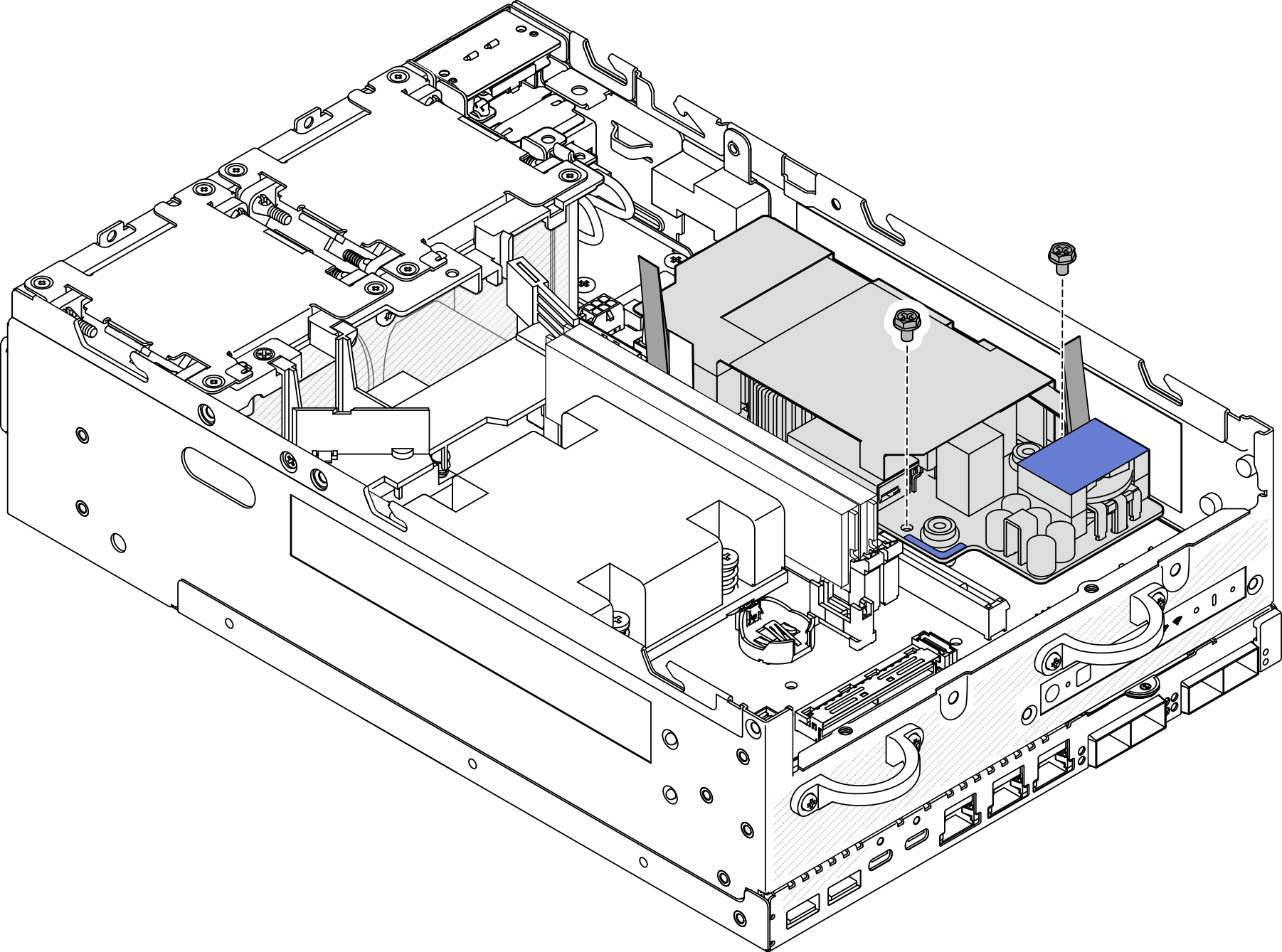
- Loosen the two screws that secure the internal power supply unit.Figure 4. Loosening the screws
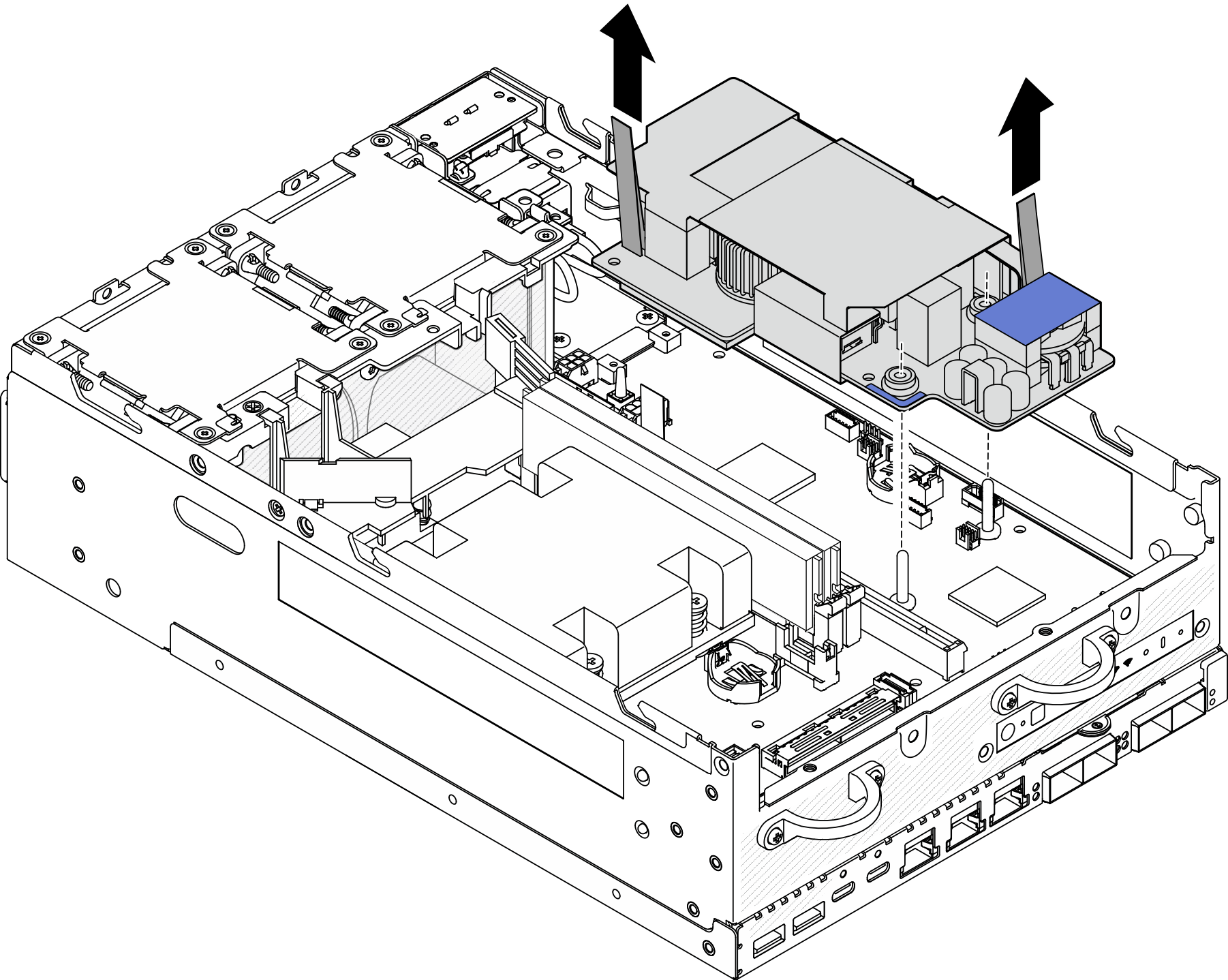
- Pinch the pull tapes to lift the internal power supply unit slightly up; then, pinch the edge of the internal power supply unit and lift it up to remove it from the chassis.Figure 5. Removing the internal power supply unit
After this task is completed
Install a replacement unit. See Install the internal power supply unit (AC PMB).
If you are instructed to return the component or optional device, follow all packaging instructions, and use any packaging materials for shipping that are supplied to you.
Demo Video