Remove the SMA assemblies
Follow instructions in this section to remove the SMA assemblies or SMA fillers.
About this task
Read Installation Guidelines and Safety inspection checklist to ensure that you work safely.
Power off the server and peripheral devices and disconnect the power cords and all external cables. See Power off the server.
If the node is installed in an enclosure or mounted, remove the node from the enclosure or mount. See Configuration guide.
See the section corresponding to the SMA assembly or the SMA filler to be removed:
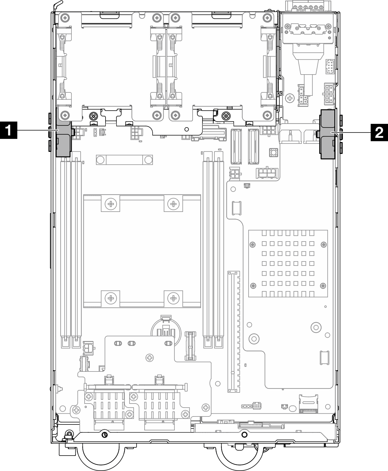
| 1 Processor side SMA assembly (SMA connector 1, 2) | 2 PMB side SMA assembly (SMA connector 3, 4) |
Remove the PMB side SMA assembly or SMA filler
- Make preparation for this task.
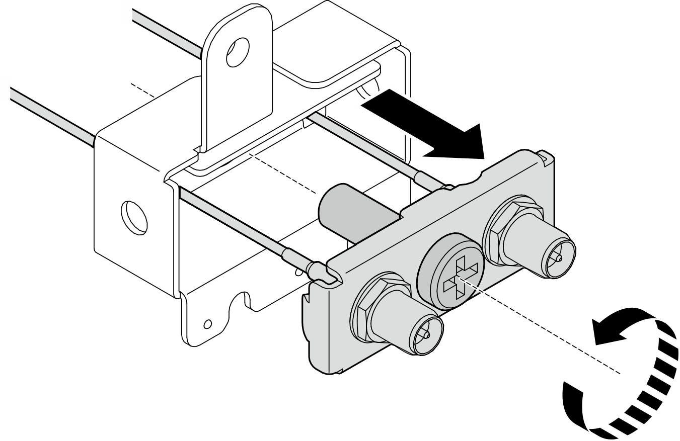
- If applicable, turn the screw between the two SMA connectors clockwise to shorten the connectors into the chassis.NoteMake sure that the SMA connectors are shortened into the chassis; if the SMA connectors are extended and out of the chassis, the SMA assembly can not be removed successfully.Figure 3. Shortening the SMA connectors
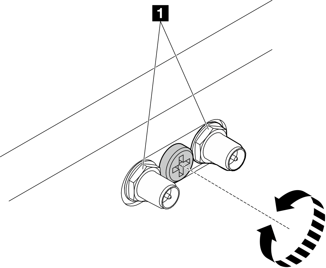
1 SMA connectors
- If applicable, turn the screw between the two SMA connectors clockwise to shorten the connectors into the chassis.
- Depending on the model, remove the SMA assembly or the SMA filler.
- For the model without wireless module, remove the SMA filler.
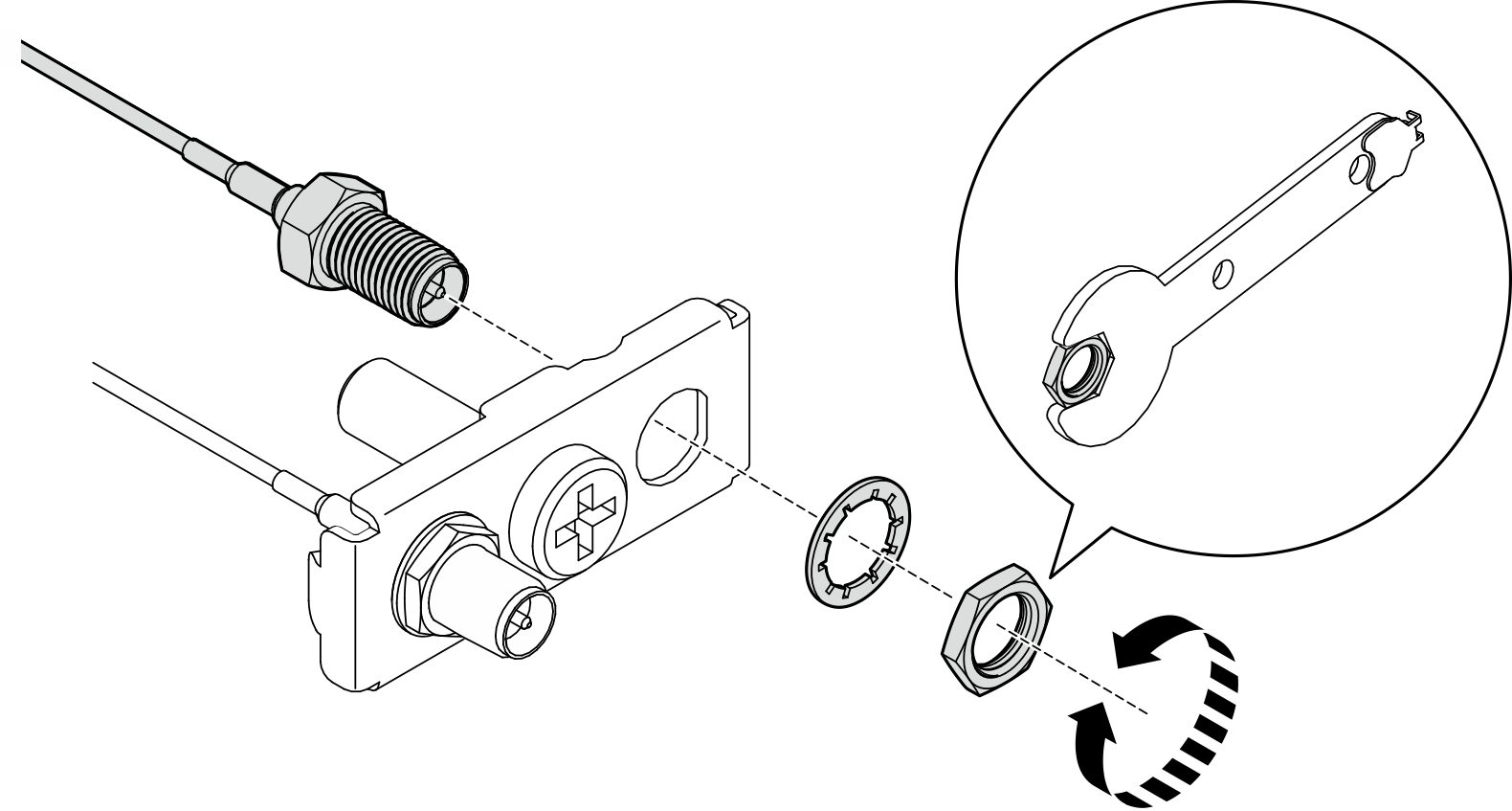
 Loosen the screw that secures the SMA filler.
 Lift the SMA filler to remove it.
Figure 4. Removing the SMA filler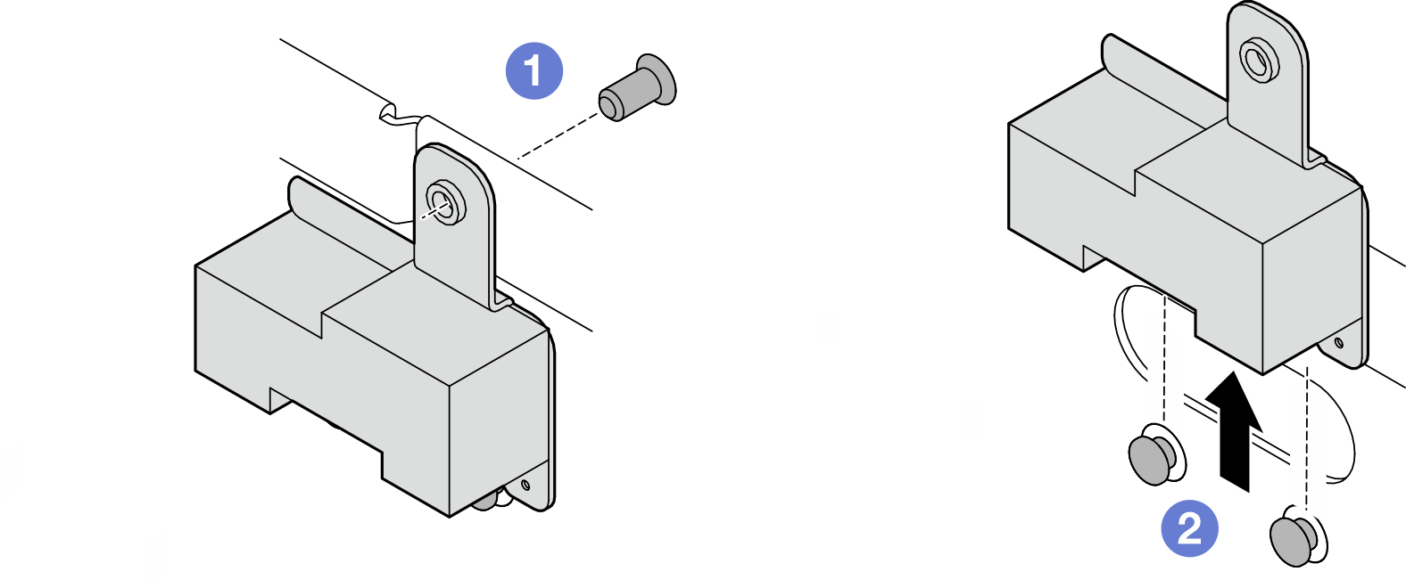
- For the model without wireless module, remove the SMA filler.
- Disconnect the cables from the WLAN/Bluetooth module.
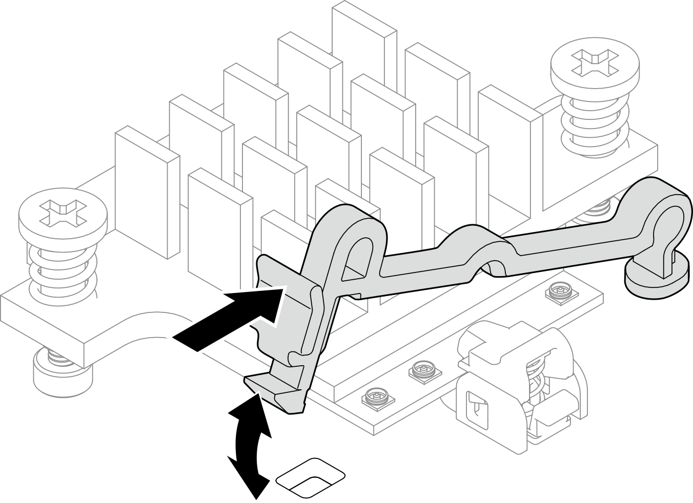
- Pinch and press the side of the cable holder; then, lift up one end of the cable holder from the wireless adapter.Figure 5. Lifting the cable holder
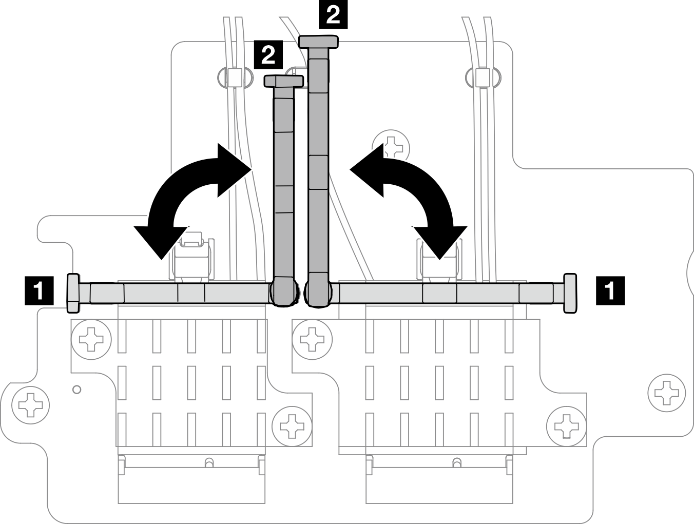
- Pivot the cable holder to 2 unlock position.Figure 6. Pivoting the cable holder
- Hook the cable with the wrench as shown; then, gently remove the cable from the connector and the cable clip.NoteRepeat this step to remove the other cable of
PMB side SMA assembly from the wireless adapter. Figure 7. Disconnecting the cable
- Pivot the cable holder to 1 lock position.Figure 8. Pivoting the cable holder
- Press the side of the cable holder; then, insert the cable holder to the slot on the wireless adapter.Figure 9. Inserting the cable holder
- Pinch and press the side of the cable holder; then, lift up one end of the cable holder from the wireless adapter.
- Remove the SMA assembly from the node.
- Loosen the screw that secures the SMA assembly.
- Lift the SMA assembly to remove it.
Figure 10. Removing the SMA assembly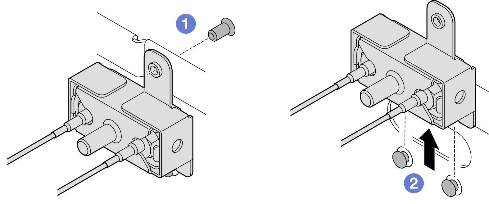
- Loosen the screw that secures the bracket; then, separate the bracket from the SMA assembly.Figure 11. Removing the bracket
- Loosen the cables with the wrench; then, remove the cables from the bracket.Figure 12. Loosening the cables from the bracket
After this task is completed
Install a replacement unit. See Install the SMA assemblies.
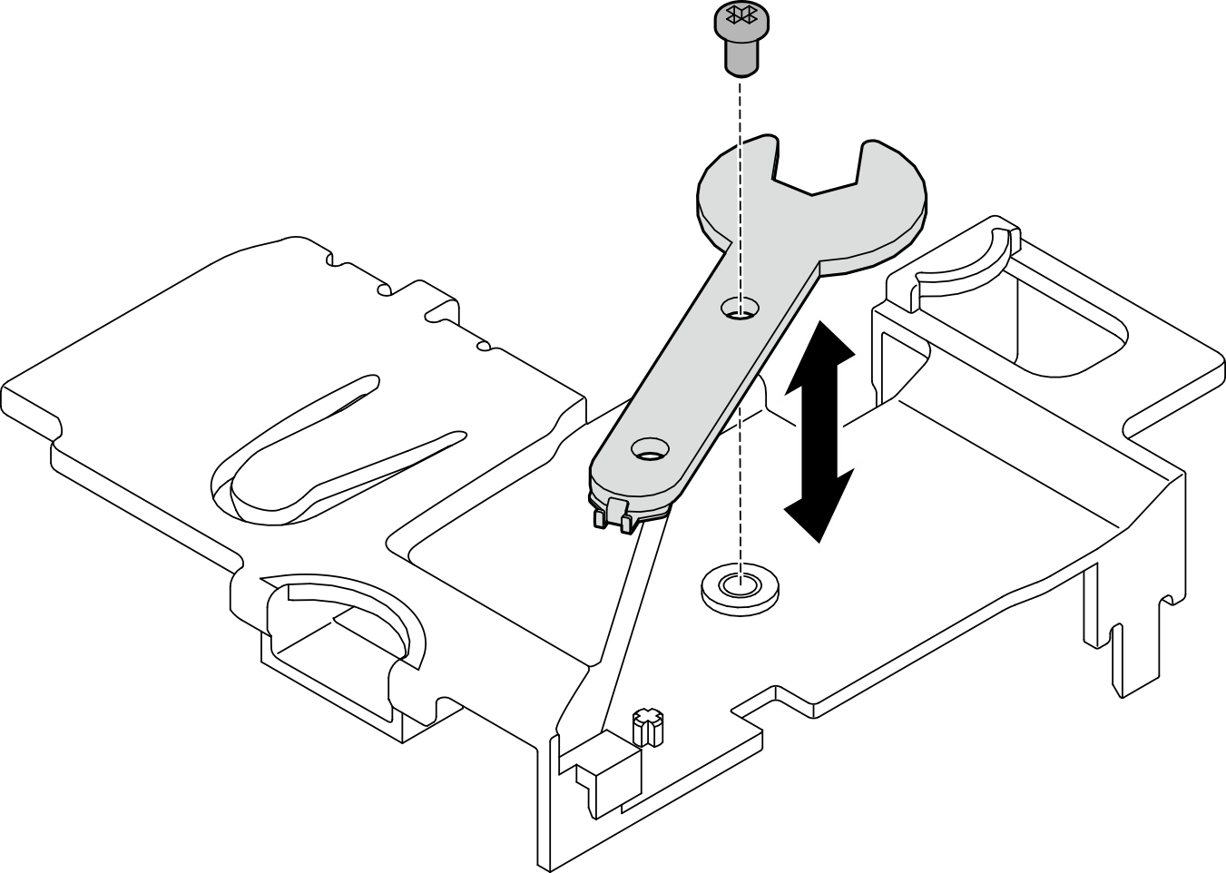
- After completing the task with the wrench that comes in the PMB air baffle, store the wrench back to the PMB air baffle for future use, and secure the wrench with one screw.Figure 13. Storing the wrench
If you are instructed to return the component or optional device, follow all packaging instructions, and use any packaging materials for shipping that are supplied to you.
Demo Video
Remove the processor side SMA assembly or SMA filler
- Make preparation for this task.
- If applicable, turn the screw between the two SMA connectors clockwise to shorten the connectors into the chassis.NoteMake sure that the SMA connectors are shortened into the chassis; if the SMA connectors are extended and out of the chassis, the SMA assembly can not be removed successfully.Figure 14. Shortening the SMA connectors
1 SMA connectors
- If applicable, turn the screw between the two SMA connectors clockwise to shorten the connectors into the chassis.
- Depending on the model, remove the SMA assembly or the SMA filler.
- For the model without wireless module, remove the SMA filler.
- Loosen the screw that secures the SMA filler.
- Lift the SMA filler to remove it.
Figure 15. Removing the SMA filler
- For the model without wireless module, remove the SMA filler.
- Disconnect the cables from the WLAN/Bluetooth module.
- Pinch and press the side of the cable holder; then, lift up one end of the cable holder from the wireless adapter.Figure 16. Lifting the cable holder
- Pivot the cable holder to 2 unlock position.Figure 17. Pivoting the cable holder
- Hook the cable with the wrench as shown; then, gently remove the cable from the connector and the cable clip.NoteRepeat this step to remove the other cable of
processor side SMA assembly from the wireless adapter. Figure 18. Disconnecting the cable - Pivot the cable holder to 1 lock position.Figure 19. Pivoting the cable holder
- Press the side of the cable holder; then, insert the cable holder to the slot on the wireless adapter.Figure 20. Inserting the cable holder
- Pinch and press the side of the cable holder; then, lift up one end of the cable holder from the wireless adapter.
- Remove the SMA assembly from the node.
- Loosen the screw that secures the SMA assembly.
- Lift the SMA assembly to remove it.
Figure 21. Removing the SMA assembly - Loosen the screw that secures the bracket; then, separate the bracket from the SMA assembly.Figure 22. Removing the bracket
- Loosen the cables with the wrench; then, remove the cables from the bracket.Figure 23. Loosening the cables from the bracket
After this task is completed
Install a replacement unit. See Install the SMA assemblies.
- After completing the task with the wrench that comes in the PMB air baffle, store the wrench back to the PMB air baffle for future use, and secure the wrench with one screw.Figure 24. Storing the wrench
If you are instructed to return the component or optional device, follow all packaging instructions, and use any packaging materials for shipping that are supplied to you.
Demo Video