Install the SMA assemblies
Follow instructions in this section to install the SMA assemblies or SMA fillers.
S002
CAUTION
The power-control button on the device and the power switch on the power supply do not turn off the electrical current supplied to the device. The device also might have more than one power cord. To remove all electrical current from the device, ensure that all power cords are disconnected from the power source.
About this task
Attention
Read Installation Guidelines and Safety inspection checklist to ensure that you work safely.
Touch the static-protective package that contains the component to any unpainted metal surface on the server; then, remove it from the package and place it on a static-protective surface.
Procedure
- Depending on the model, install the SMA assemblies or SMA fillers.
- For models without wireless module, install the SMA fillers.
 Align the notches of the SMA filler with the guide pins on the chassis; then, carefully lower the SMA filler until it is firmly seated.
 Secure the SMA filler with one screw.
Figure 1. Installing the SMA filler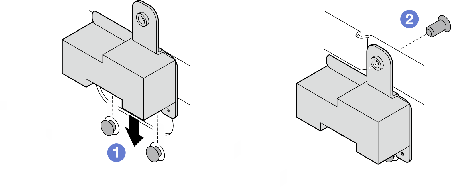
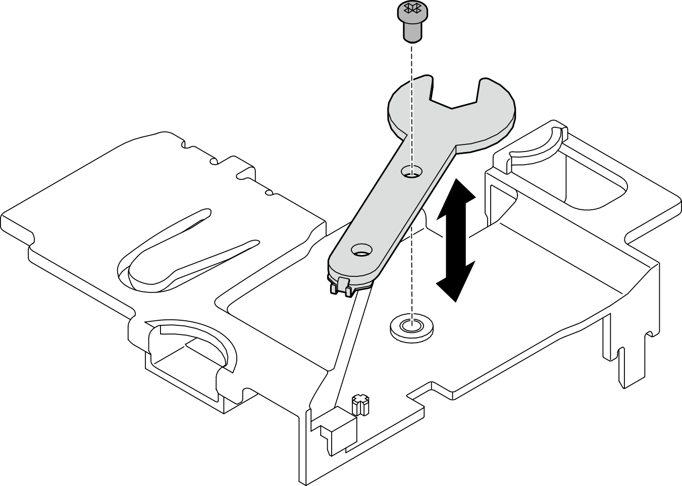
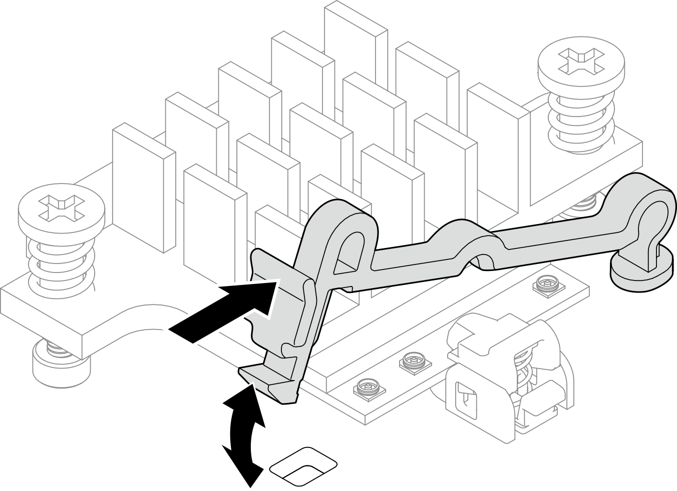
- For models with wireless module, complete the following steps to install SMA assemblies..NoteThis task requires a wrench. If necessary, use the wrench that comes in the PMB air baffle. Loosen the screw that secures the wrench to disengage the wrench from the air baffle.Figure 2. Disengaging the wrench
- For models without wireless module, install the SMA fillers.
- Locate the SMA assembly to be installed:Figure 3. SMA assembly locations
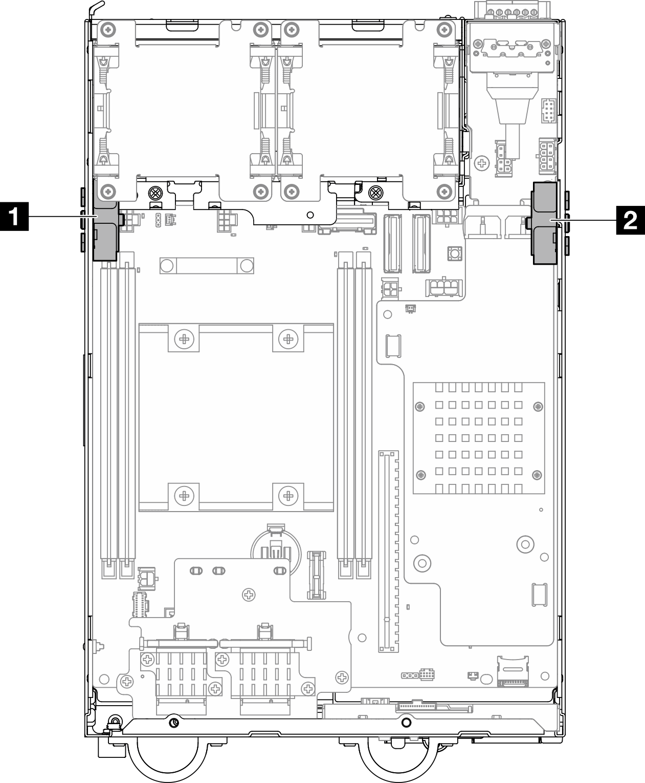
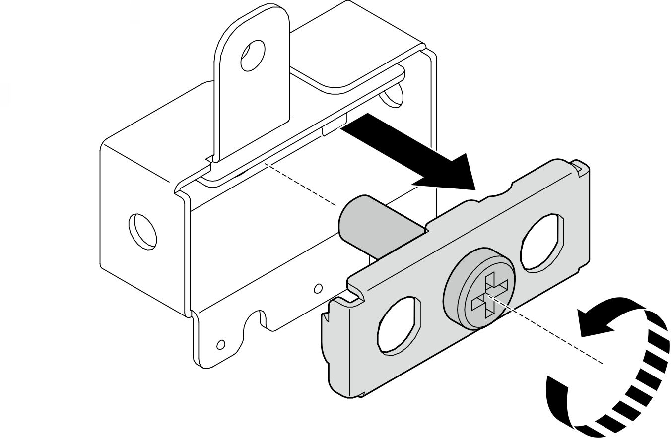
1 Processor side SMA assembly (SMA connector 1, 2) 2 PMB side SMA assembly (SMA connector 3, 4) - If the bracket is secured to the SMA assembly, loosen the screw that secure the bracket; then, separate the bracket from the SMA assembly.Figure 4. Removing the bracket
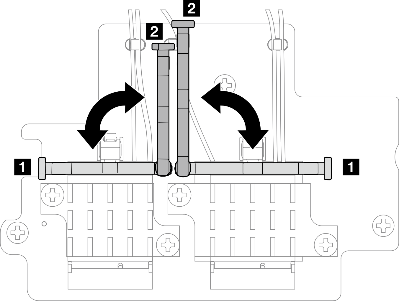
- Fasten the cables to the bracket with the wrench.
- For the processor side SMA assembly: Fasten the gray cable (XCC WLAN #1) and the white cable (XCC WLAN #2).
- For PMB side SMA assembly: Fasten the blue cable (x86 WLAN #3) and the black cable (x86 WLAN #4).
Figure 5. Fastening the cables to the bracket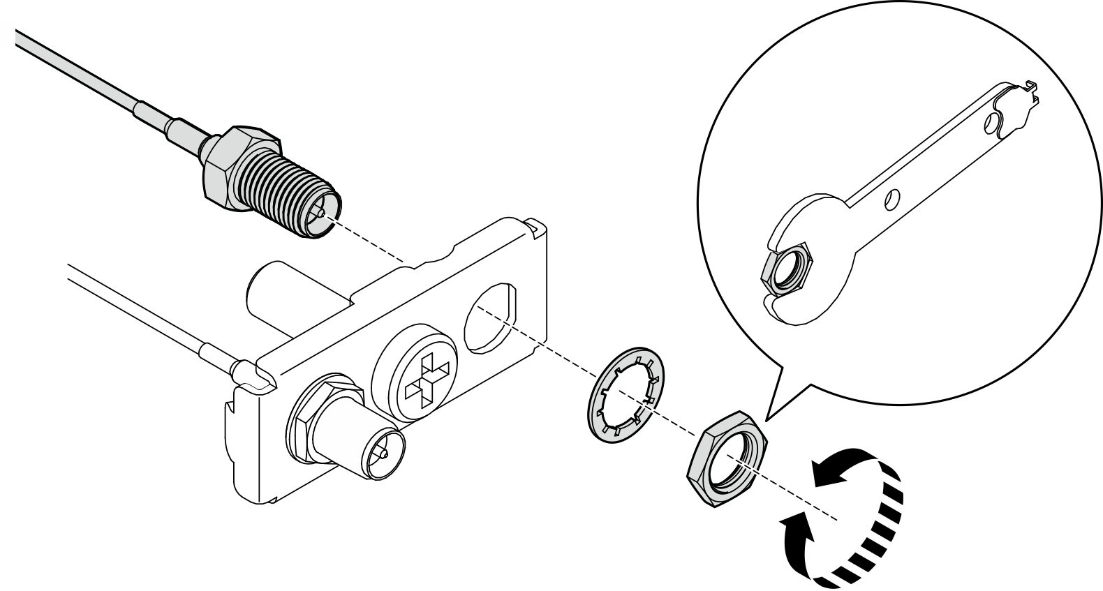
- Insert the bracket into the SMA assembly until it is firmly seated; then, secure the bracket with one screw.Important
- Fully fasten the screw until the SMA connectors are inside the SMA assembly. If the SMA connectors are out of the SMA assembly, the SMA assembly can not be installed successfully.
- Make sure the order of the cables is as shown in the following illustrations.
- For the processor side SMA assembly:
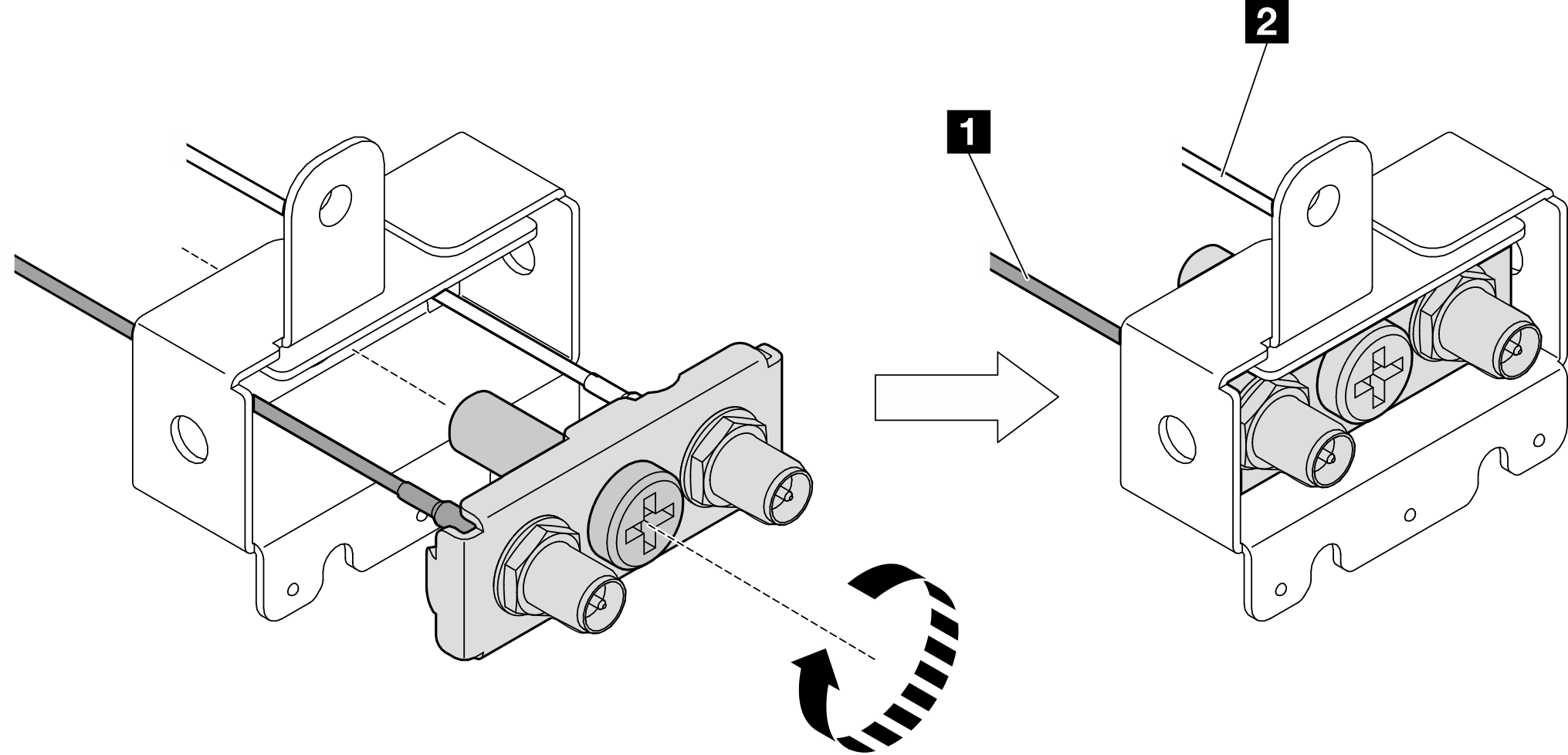
1 The gray cable (XCC WLAN #1) 2 The white cable (XCC WLAN #2) - For the PMB side SMA assembly:
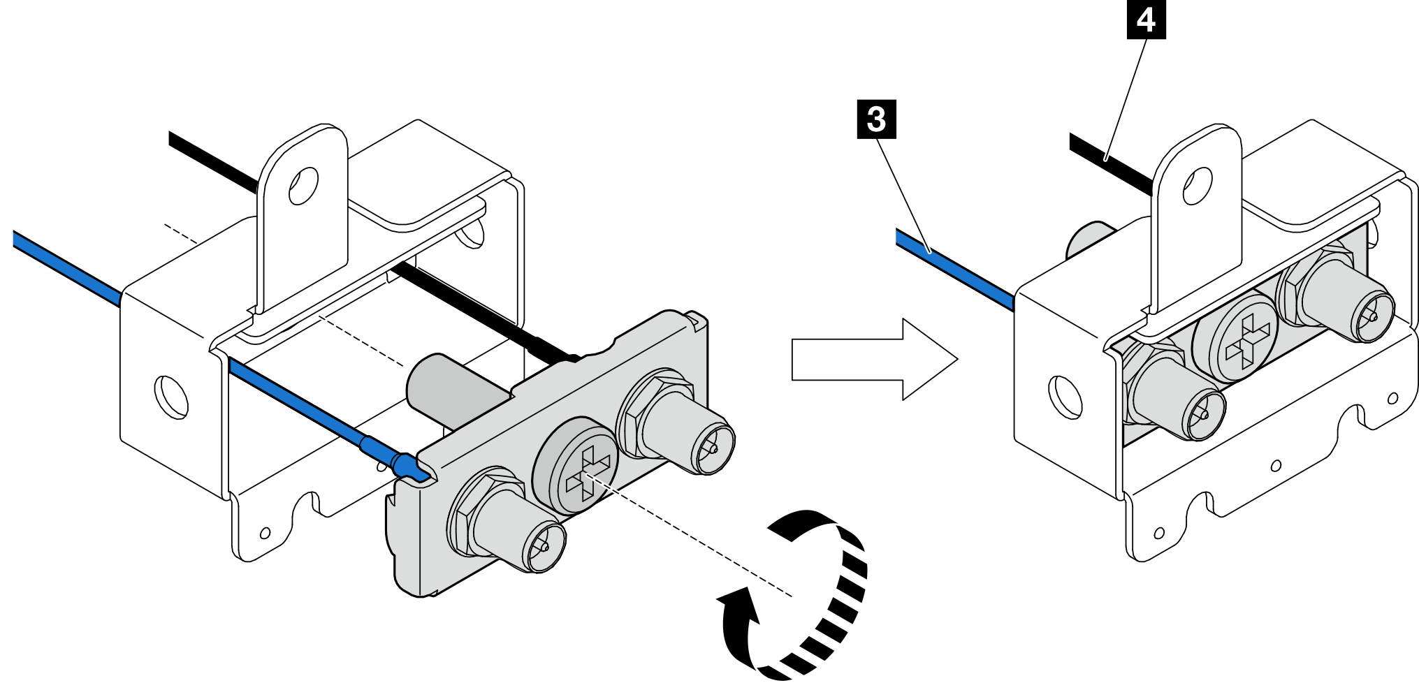
3 The blue cable (x86 WLAN #3) 4 The black cable (x86 WLAN #4)
- For the processor side SMA assembly:
- Install the SMA assembly.
- Align the notches of the SMA assembly with the guide pins on the chassis; then, carefully lower the SMA assembly until it is firmly seated.
- Secure the SMA assembly with one screw.
Figure 6. Installing the SMA assembly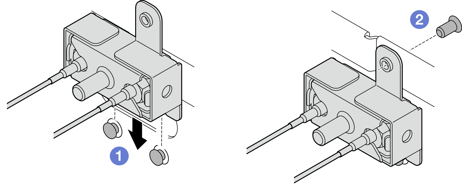
- Route the cables.Figure 7. Cable routing for the SMA assemblies
 NoteThe orientation of the following table aligns with the above illustration.
Cable 3 x86 WLAN #3 4 x86 WLAN #4 1 XCC WLAN #1 2 XCC WLAN #2 Color Blue Black Gray White From SMA connector 3 SMA connector 4 SMA connector 1 SMA connector 2 To Connector 1 of x86 WLAN module Connector 2 of x86 WLAN module The left connector of XCC WLAN and Bluetooth module The center connector of XCC WLAN and Bluetooth module - Connect the cables to the wireless adapter.
- Pinch and press the side of the cable holder; then, lift up one end of the cable holder from the wireless adapter.Figure 8. Lifting the cable holder
- Pivot the cable holder to 2 unlock position.Figure 9. Pivoting the cable holder
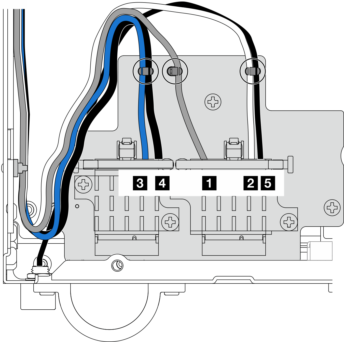
- Locate the corresponding connector.Figure 10. Cable routing for wireless adapter
 NoteThe orientation of the following table aligns with the above illustration.
Cable 3 x86 WLAN #3 4 x86 WLAN #4 1 XCC WLAN #1 2 XCC WLAN #2 5 Bluetooth #5 Color Blue Black Gray White Black From SMA connector 3 SMA connector 4 SMA connector 1 SMA connector 2 Bluetooth antenna To Connector 1 of x86 WLAN module Connector 2 of x86 WLAN module The left connector of XCC WLAN and Bluetooth module The center connector of XCC WLAN and Bluetooth module The right connector of XCC WLAN and Bluetooth module - Gently press the cable connector down until it clicks in the connector on the WLAN module.NoteRepeat this step to connect all the necessary cables to the WLAN/Bluetooth modules.Figure 11. Connecting the cable

- Pivot the cable holder to 1 lock position.Figure 12. Pivoting the cable holder
- Press the side of the cable holder; then, insert the cable holder to the slot on the wireless adapter. Make sure the cables are secured by the cable holder.Figure 13. Inserting the cable holder
- Secure the cables into the cable clips on the wireless adapter; then, route the cables to the corner of the chassis.Figure 14. Cable routing for wireless adapter
- Pinch and press the side of the cable holder; then, lift up one end of the cable holder from the wireless adapter.
After this task is completed
- After completing the task with the wrench that comes in the PMB air baffle, store the wrench back to the PMB air baffle for future use, and secure the wrench with one screw.Figure 15. Storing the wrench
If applicable, reconnect the following cables.
Fan cables
Fan direction switch cable
Intrusion switch cable
Complete the parts replacement. See Complete the parts replacement.
Demo Video
Give documentation feedback