Install the power module board (PMB)
Follow instructions in this section to install the power module board (PMB).
About this task
Read Installation Guidelines and Safety inspection checklist to ensure that you work safely.
Touch the static-protective package that contains the component to any unpainted metal surface on the server; then, remove it from the package and place it on a static-protective surface.
Procedure
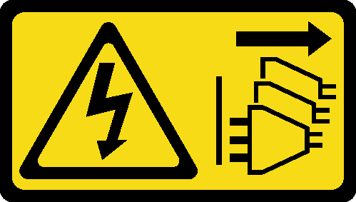
- Make sure the signal cable between the front operator panel and rear operator panel is placed outside the chassis.Figure 1. Placing the signal cable
- Install the power module board.
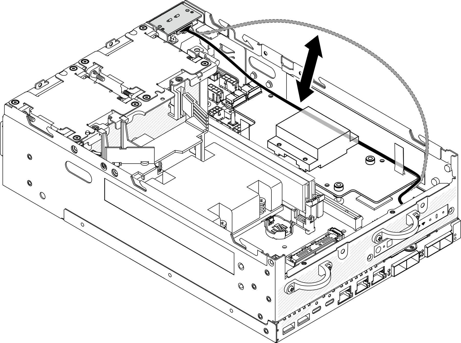
 Connect the power cables from the PIB module to the power module board.
 Align the power module board with the busbars on the system board; then, lower the power module board down until it is firmly seated.
ImportantMake sure that the busbars are seated in the holes of power module board as shown in the illustration.Figure 2. Installing the power module board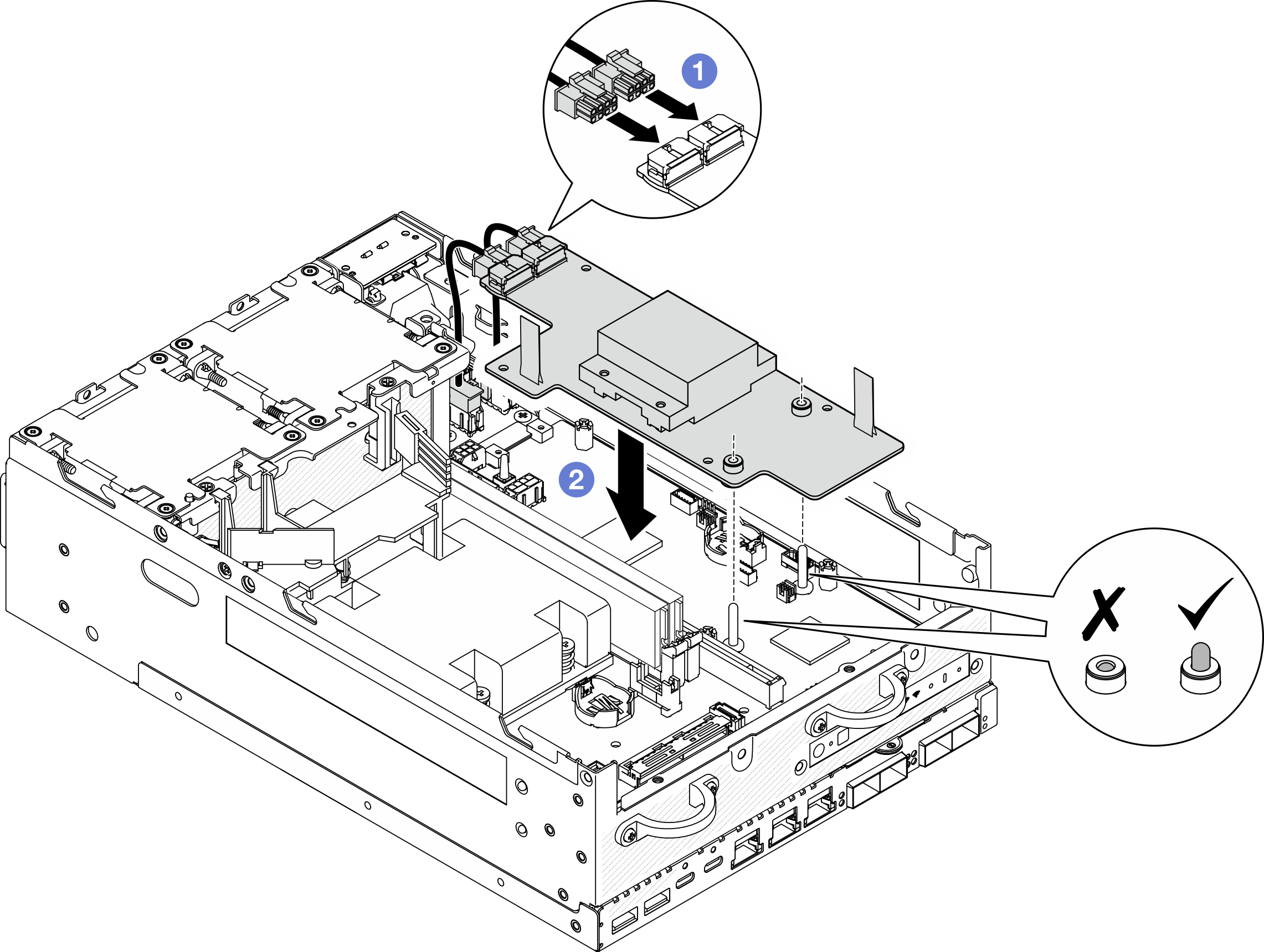 Note
NoteDo not let the pull tapes be bent or covered. Make sure the pull tapes are on the upper side of the power module board.
Make sure that the slots for PMB air baffle are not interfered by the cables between the power module board and the PIB module.
Figure 3. The slots for PMB air baffle
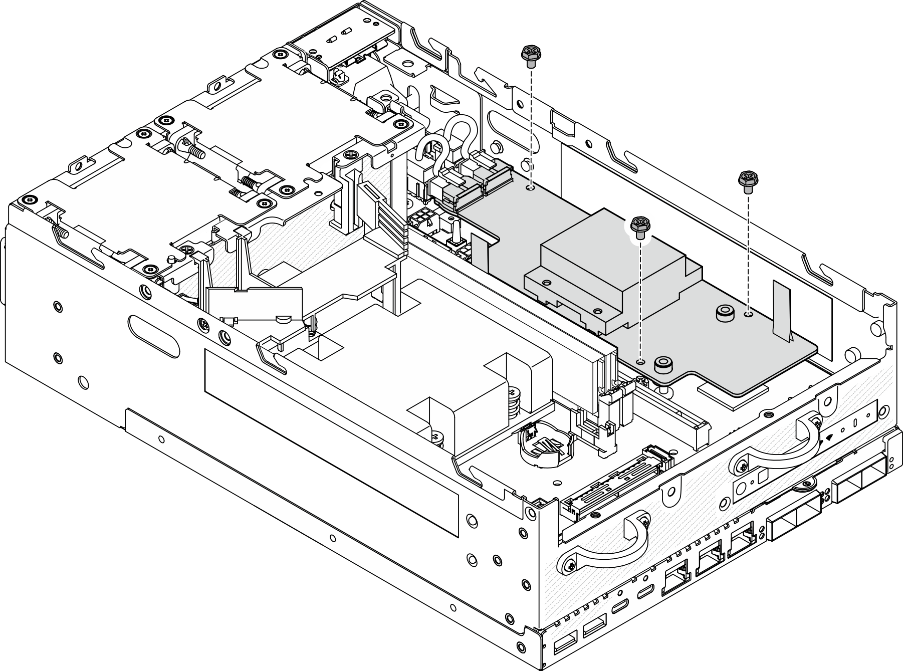
- Secure the power module board with three screws.Figure 4. Securing the power module board
- Connect the PMB LED cable to the power module board.Figure 5. PMB LED cable
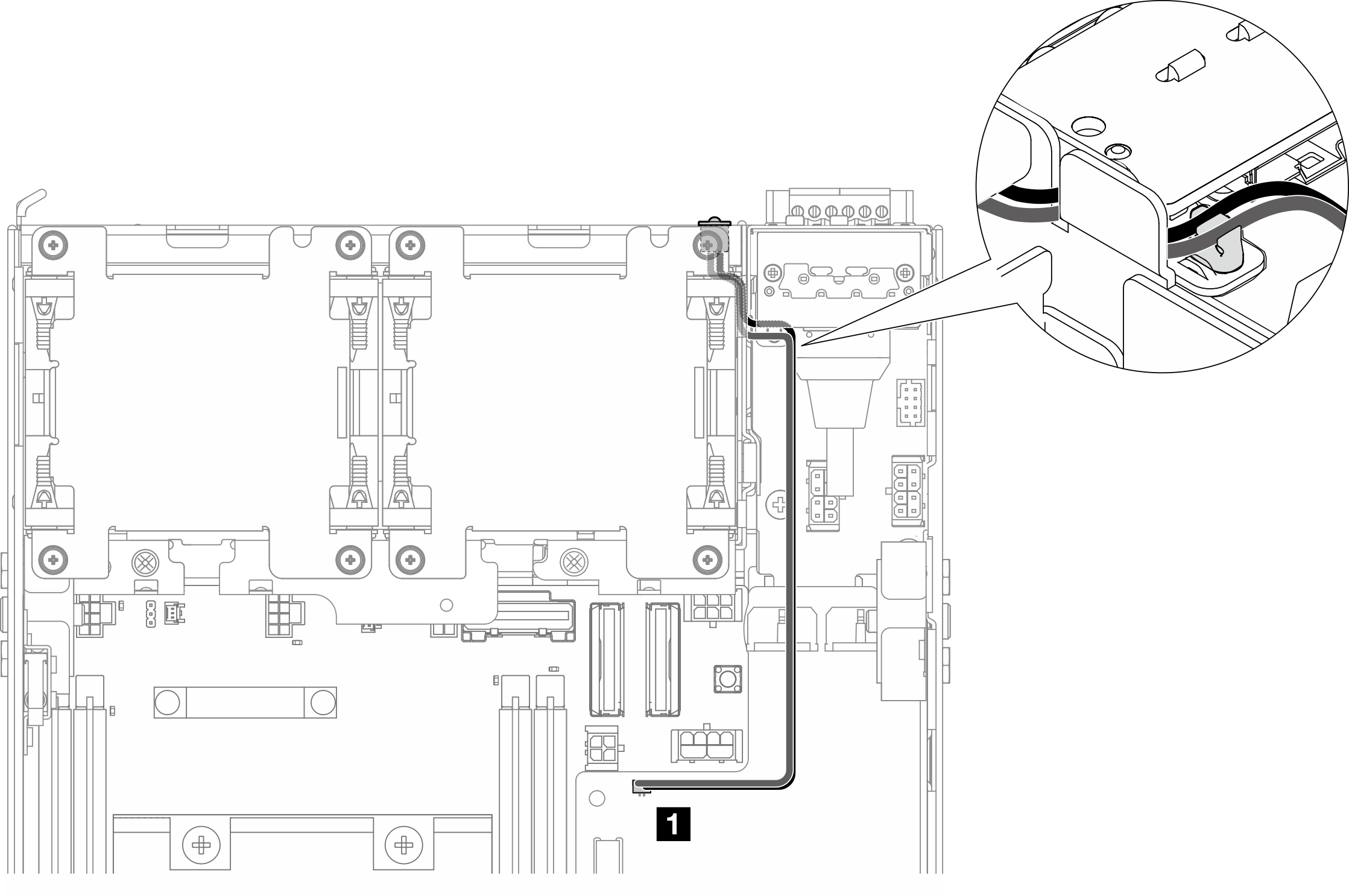
1 PMB status LED connector on the power module board
After this task is completed
Place the signal cable between the front operator panel and rear operator panel back into the chassis.
Figure 6. Placing the signal cableComplete the parts replacement. See Complete the parts replacement.
Demo Video