System-board connectors
The following illustrations show the internal connectors on the system board.
Figure 1. System-board connectors
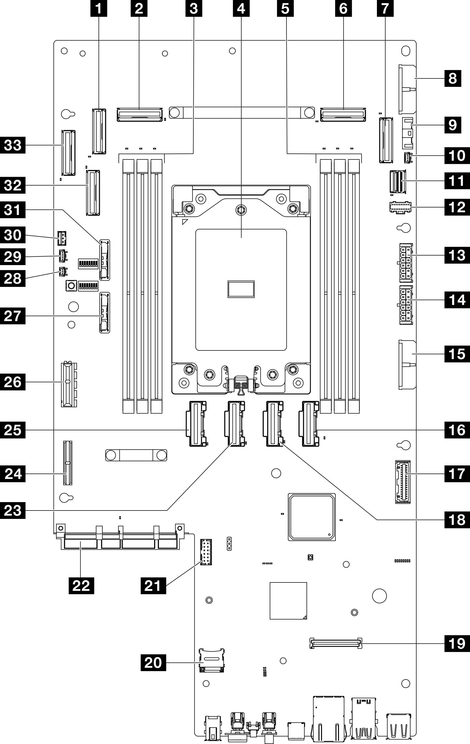
| 1 PCIe 9 connector | 18 PCIe 5 connector |
| 2 PCIe 8 connector | 19 Firmware and RoT security module connector |
| 3 Memory module slots (DIMM 4-6, right to left) | 20 MicroSD socket |
| 4 Processor | 21 Serial port connector (COM) |
| 5 Memory module slots (DIMM 1-3, right to left) | 22 OCP module connector |
| 6 PCIe 3 connector | 23 PCIe 6 connector |
| 7 PCIe 2 connector | 24 Riser 1 power connector |
| 8 System board power 2 connector (PDB PWR 2) | 25 PCIe 7 connector |
| 9 Fan signal connector (FCB Sideband) | 26 Riser 1 signal connector (Riser1 Sideband) |
| 10 Heat sink detect connector | 27 3V system battery (CR2032) |
| 11 M.2 signal connector (PCIe 1) | 28 Bezel detect connector |
| 12 M.2 power connector (M.2 Sideband) | 29 Air flow sensor board connector (Air Velocity Sensor) |
| 13 Internal backplane power connector | 30 Intrusion switch connector |
| 14 Front backplane power connector | 31 3V security battery (CR2032) |
| 15 System board power 1 connector (PDB PWR 1) | 32 PCIe 10 connector |
| 16 PCIe 4 connector | 33 PCIe 11 connector |
| 17 Power distribution board signal connector (PDB Sideband) |
Give documentation feedback