Front view
This section contains information about the controls, LEDs, and connectors on the front of the server.
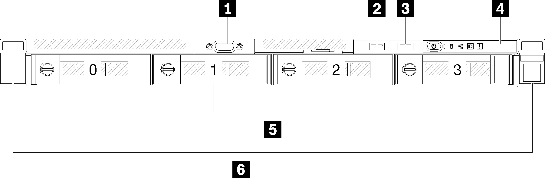
| 1 VGA connector | 4 Front operator panel |
| 2 USB 2.0 connector (with Lenovo XClarity Controller) | 5 Simple-swap drive bays (numbering 0-3, matching SATA port 4-7 on system board, see System-board connectors) |
| 3 USB 3.1 Gen1 connector | 6 Rack latches |
1 VGA connector:
- When the front VGA connector is in use, the rear VGA connector will be disabled.
- The maximum video resolution is 1600x1200 at 75 Hz.
2 3 USB connectors:
USB 1: USB 2.0 with Lenovo XClarity Controller management
USB 2: USB 3.1 Gen1
4 Front operator panel
Front operator panel contains several LED and buttons, see Front operator panel for more information.
5 Simple-swap drives:
Install drives into these bays. See Install a simple-swap disk drive for more details.
When SATA drives are installed and connected to SATA connectors 4-7 on system board (without a RAID adapter installed), the drive number will be reported by RAID utility as drives 4, 5, 6, and 7 (different from drive bay number)
When SAS or SATA drives are installed and connected to RAID adapter, the drive number will be 0, 1, 2, and 3 (same as drive bay number)
Drive bay 2 and 3 are not available when the two-drive backplate is installed.
6 Rack latches:
Pull the latch on both sides in the front of the server to remove the server out of the rack.