System-board connectors
Use this information to locate system-board components and connectors for optional devices.
The following illustration shows the system-board components, including connectors for user-installable optional devices, in the server.
Figure 1. System-board connectors
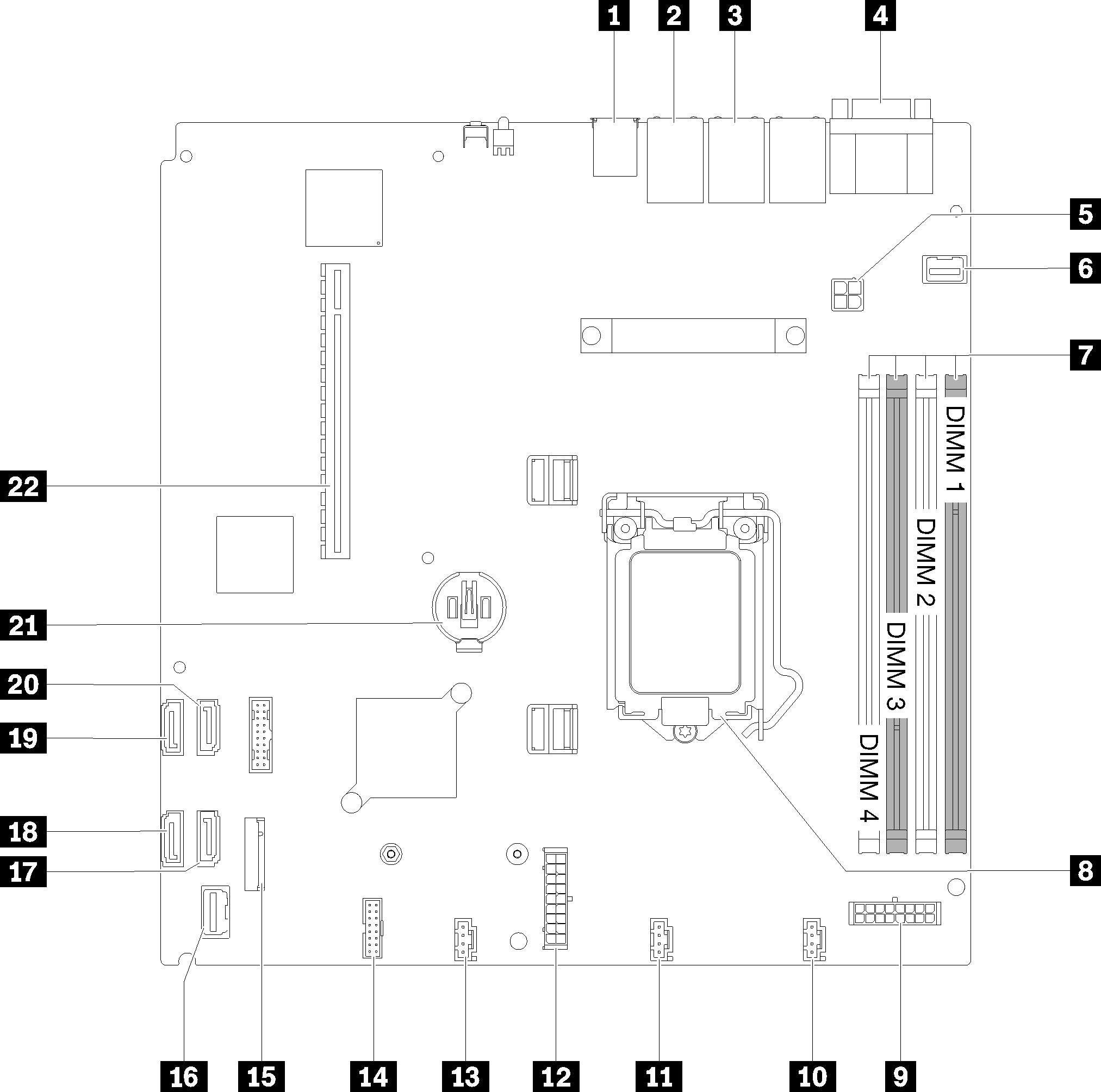
| 1 USB connector | 12 System power connector |
| 2 LAN 2 connector | 13 Fan 3 connector |
| 3 LAN 1 connector (shared with Lenovo XClarity Controller) | 14 TPM card connector |
| 4 Serial port connector (upper) and VGA connector (bottom) | 15 M.2 connector |
| 5 Processor power connector | 16 Front operator panel connector |
| 6 Front VGA connector | 17 SATA 6 connector |
| 7 DIMM connectors | 18 SATA 7 connector |
| 8 Processor socket | 19 SATA 4 connector |
| 9 Backplate power connector | 20 SATA 5 connector |
| 10 Fan 1 connector | 21 CMOS battery connector |
| 11 Fan 2 connector | 22 PCIe slot |
Give documentation feedback