System-board jumpers and buttons
The following illustrations show the location of the jumpers and buttons on the server.
Note
If there is a clear protective sticker on the top of the switch blocks, you must remove and discard it to access the switches.
Figure 1. System-board jumpers and buttons
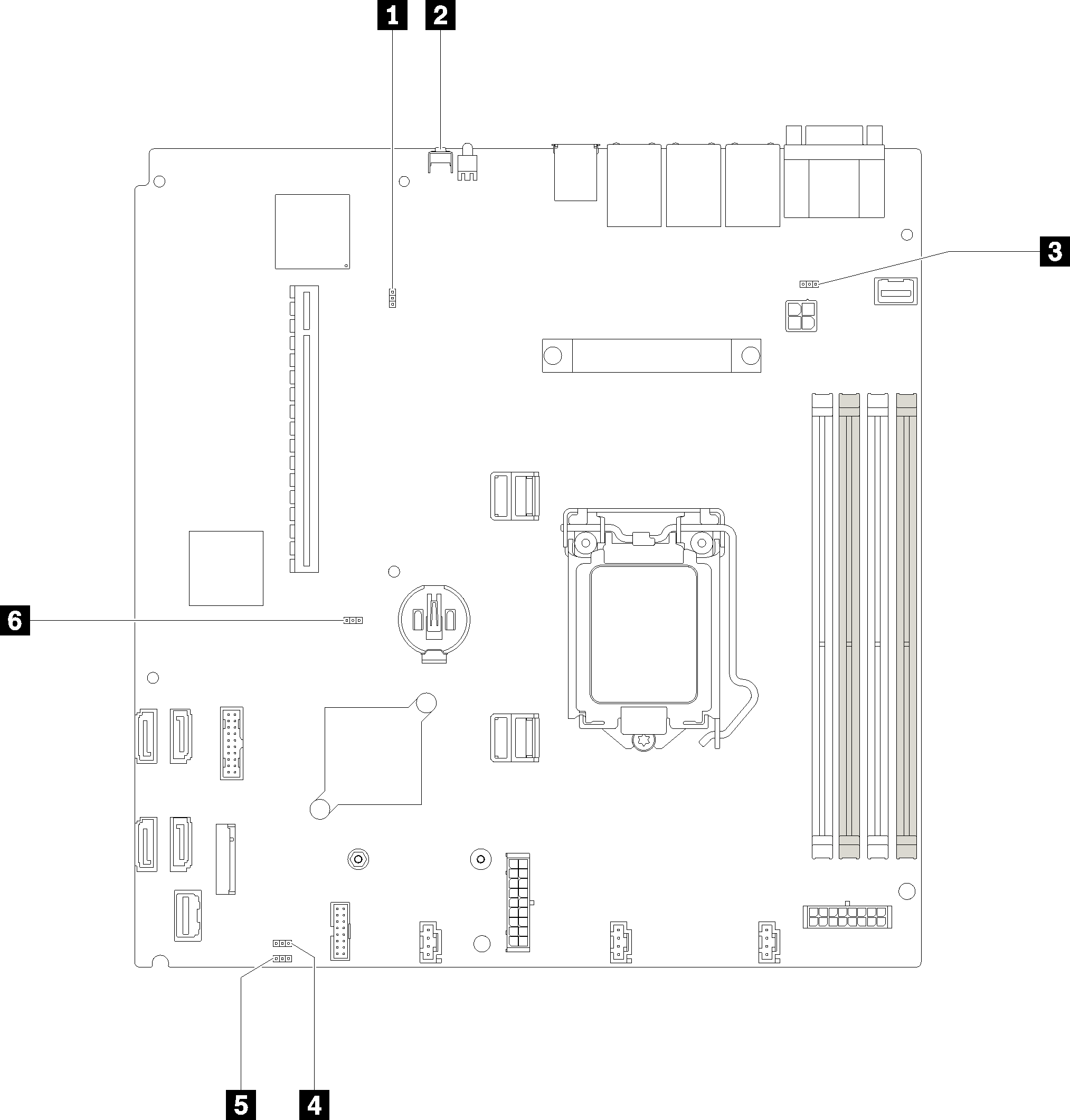
| Jumper and button name | Jumper setting / button function |
| 1 Force XCC update jumper |
|
| 2 NMI button | Press this button to force a nonmaskable interrupt (NMI) to the processor. By this way, you can set the server into blue screen mode and take a memory dump. |
| 3 NCSI function |
|
| 4 Power permission override jumper |
|
| 5 Clear CMOS jumper |
|
| 6 TPM card physical presence jumper |
|
Important
- Before you change any switch settings or move any jumpers, turn off the server; then, disconnect all power cords and external cables. Review the information in Safety Information page, Installation Guidelines, Handling static-sensitive devices, and Power off the server.
- Any system-board switch or jumper block that is not shown in the illustrations in this document are reserved.
Give documentation feedback