Install the 3.5-inch-drive backplane
Use this information to install the 3.5-inch-drive backplane. This topic applies only to server models that support 3.5-inch-drive backplanes.


Before installing the 3.5-inch-drive backplane, touch the static-protective package that contains the new backplane to any unpainted surface on the outside of the server. Then, take the new backplane out of the package and place it on a static-protective surface.
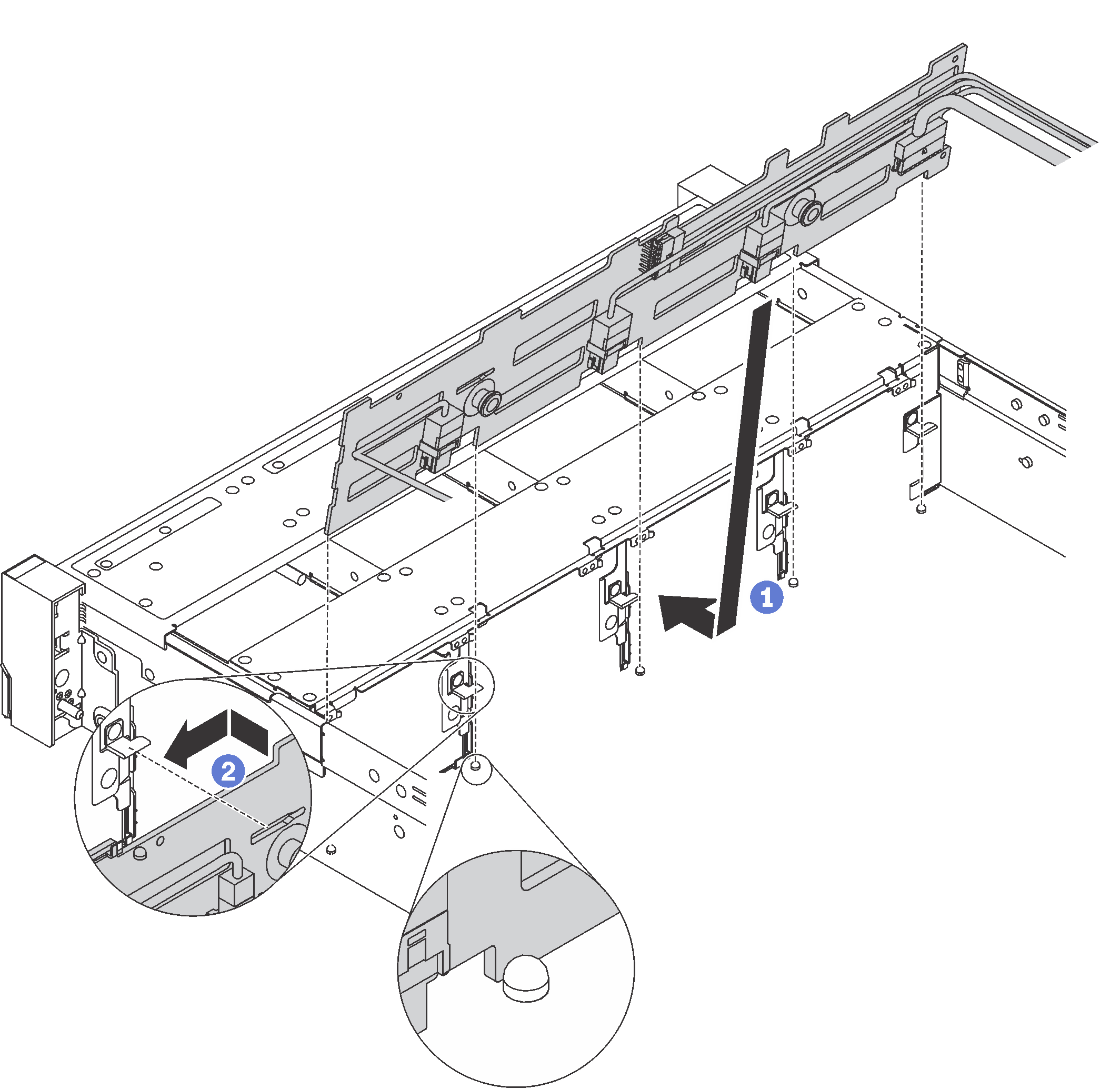
To install the 3.5-inch-drive backplane, complete the following steps:
Watch the procedure
A video of this procedure is available at YouTube.
- Apply the drive bay label based on the type of the installed backplane. The drive bay label comes with each type of the supported drive backplane:
0–7
Apply this label to the chassis if an 8-bay backplane is installed.
0–11
Apply this label to the chassis if a 12-bay backplane is installed.
0–11 (NVMe)
Apply this label to the chassis if an AnyBay 12-bay backplane is installed.
NoteNVMe drives are supported in drive bays 8–11.
The following illustration shows the location for applying the drive bay label to the server models with a 12-bay backplane installed. The location is the same for applying the drive bay label to server models with an 8-bay backplane or an AnyBay 12-bay backplane installed. Ensure that the drive bay label is stuck in the correct location. The label helps you to locate the correct drive during problem determination.Figure 2. Drive bay label for server models with a 12-bay backplane installed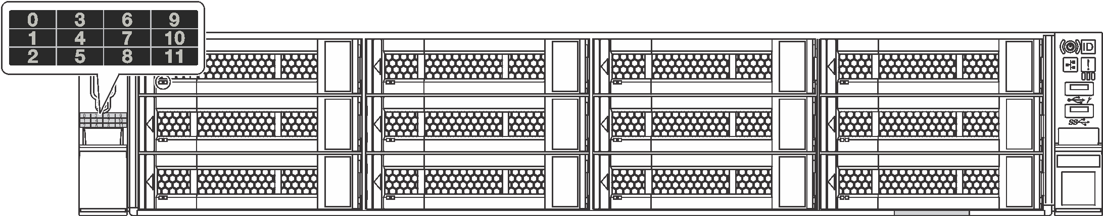
After installing the 3.5-inch-drive backplane, connect the cables to the system board. For information about the cable routing, see Internal cable routing.