Internal cable routing
See this section to do cable routing for specific components.
Some of the components in the server have internal cables and cable connectors. For details, see the following cable routing sections:
Read the following guidelines carefully before you connect any cables:
Power off the server before you connect or disconnect any internal cables.
See the documentation that comes with any external devices for additional cabling instructions. It might be easier for you to route cables before you connect the devices to the server.
Cable identifiers of some cables are printed on the cables that come with the server and optional devices. Use these identifiers to connect the cables to the correct connectors.
- Ensure that the relevant cables pass through the cable clips.
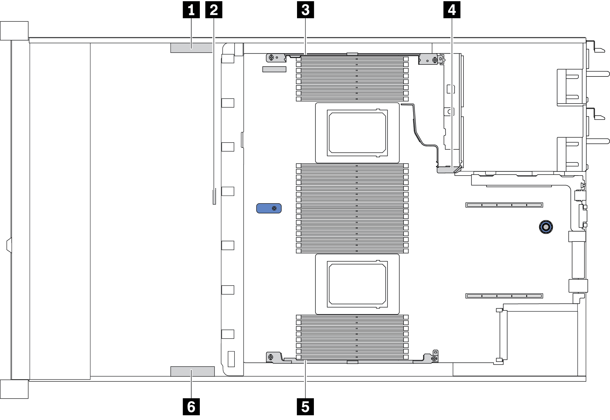
Cable holder Route 1 3 4 Route to BP Pwr connector, RAID Pwr connector, and PCIe connectors (3, 4, 5, 6) 2 Route to intrusion switch cable 5 6 Route to FIO connector, LCD external connector, M.2 Pwr connector, VGA connector, Front USB connector, PCIe connectors (1, 2, 7, 8), 7mm/M.2 connector, SATA connectors (0, 1, 2), and RAID/HBA connectors
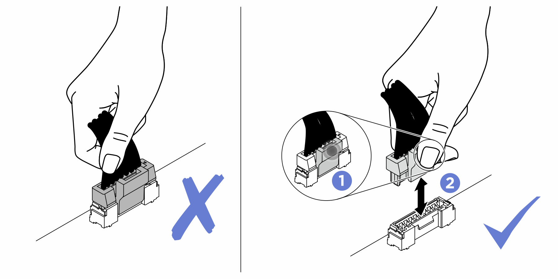
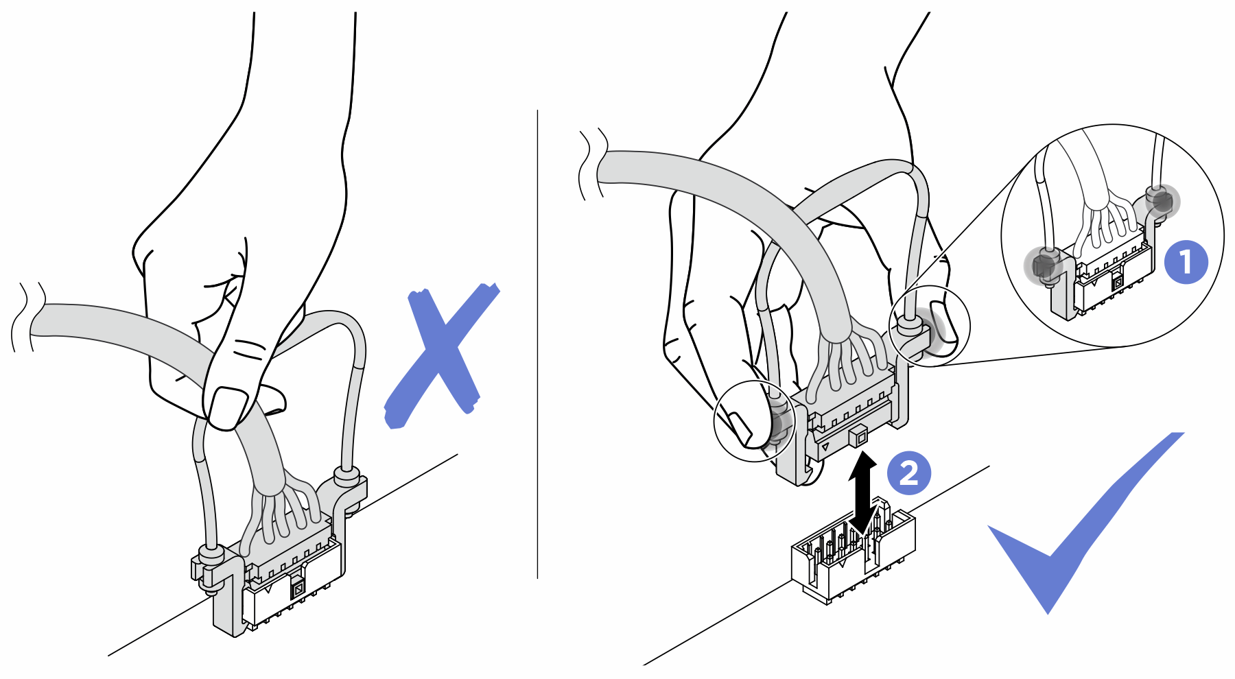
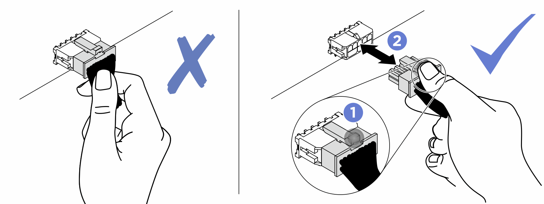
Attention
Strictly observe the following instructions to avoid damaging cable sockets on the system board. Any damage to the cable sockets might require replacing the system board.
Connect cable connectors vertically or horizontally in alignment with the orientations of the corresponding cable sockets, avoiding any tilt.
- To disconnect cables from the system board, do as follows:
Press and hold all latches, release tabs, or locks on cable connectors to release the cable connectors.
- Remove the cable connectors vertically or horizontally in alignment with the orientations of the corresponding cable sockets, avoiding any tilt.NoteThe cable connectors might look different from those in the illustration, but the removal procedure is the same.
Give documentation feedback