RAID flash power modules
Use the section to understand the cable routing for RAID flash power modules.
RAID flash power module locations
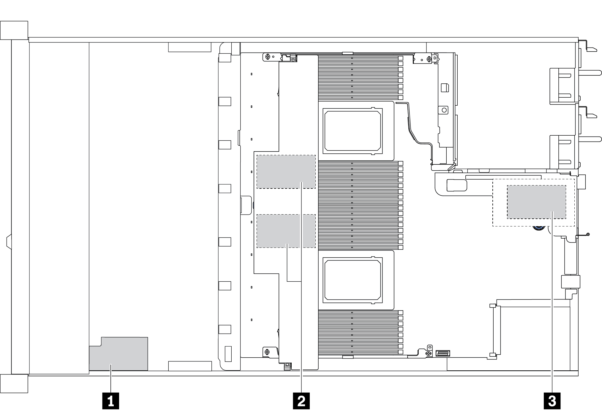
| Callout | Location | Scenario |
|---|---|---|
| 1 | Super capacitor on the chassis | 2.5'' chassis installed with a standard or performance heat sink |
| 2 | Super capacitors in the air baffle | 2.5'' or 3.5'' chassis installed with a standard heat sink |
| 3 | Super capacitors in the riser 1 slot | 3.5'' chassis installed with a performance heat sink |
An extension cable is provided for each RAID flash power module for connection. Connect the super capacitor cable to the super capacitor connector on the corresponding RAID adapter as shown.
Figure 1. Power cable routing for super capacitor
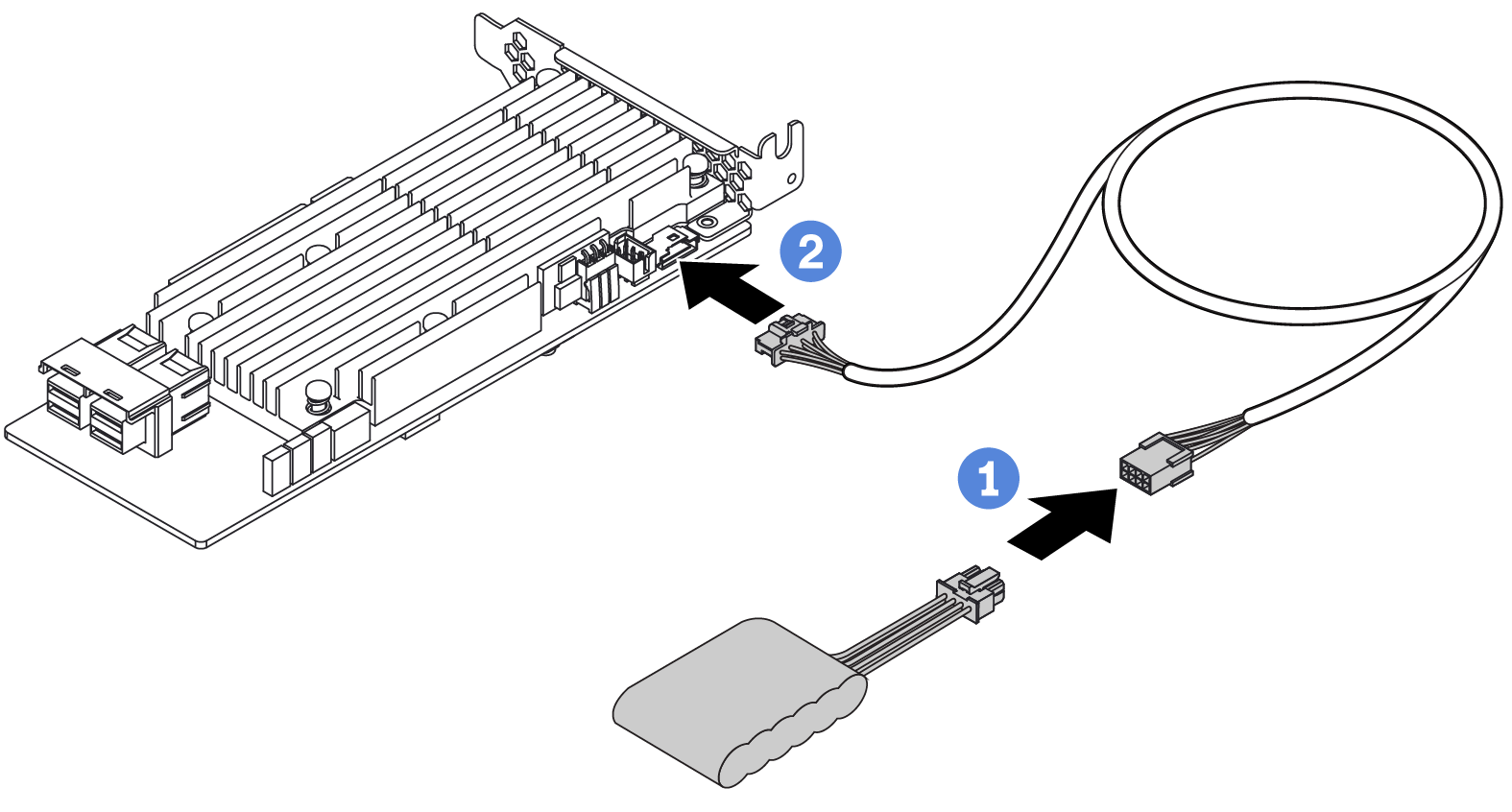
| From | To |
|---|---|
| RAID flash power module | Super capacitor connector on the RAID adapter |
Give documentation feedback