Switch block
The following illustrates the location and functions of the switch block on the system board.
- Before you move any switch, turn off the server; then, disconnect all power cords and external cables. Do not open your server or attempt any repair before reading and understanding the following information:
- If there is a clear protective sticker on the top of the switch block, you must remove and discard it to access the switches.
- Any system-board switch or jumper block that is not shown in the illustrations in this document is reserved.
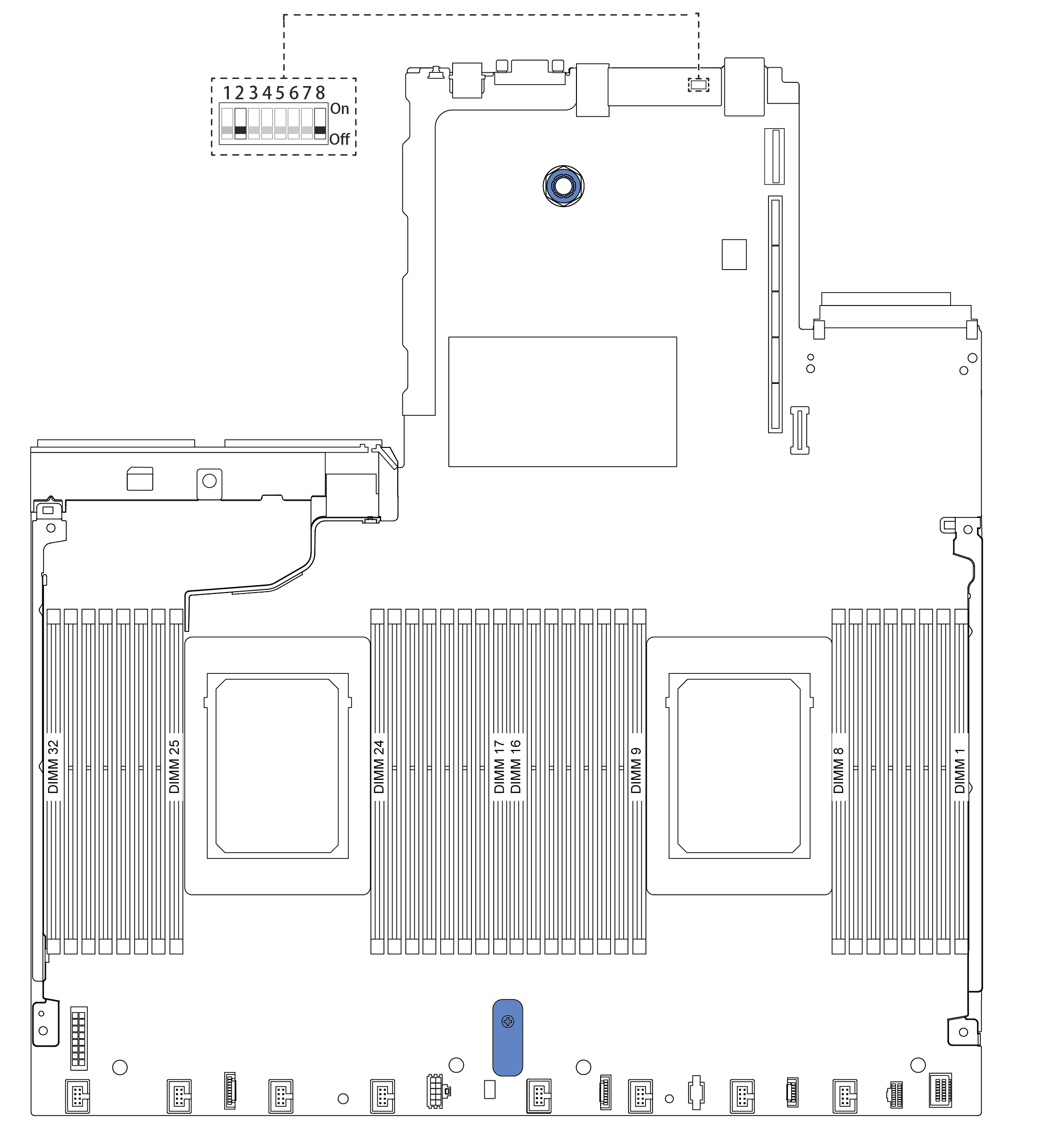
| Switch number | Switch name | Description |
|---|---|---|
| 1 SW8-1 | ME firmware security override switch |
|
| 2 SW8-2 | Clear CMOS switch |
|
| 3 SW8-3 | Force XCC reset switch |
|
| 4 SW8-4 | Force XCC update switch |
|
| 5 SW8-5 | XCC SPI0 half ROM switch |
|
| 6 SW8-6 | Low security switch |
|
| 7 SW8-7 | Reserved | Reserved |
| 8 SW8-8 | Override power-on password switch |
|