System board components
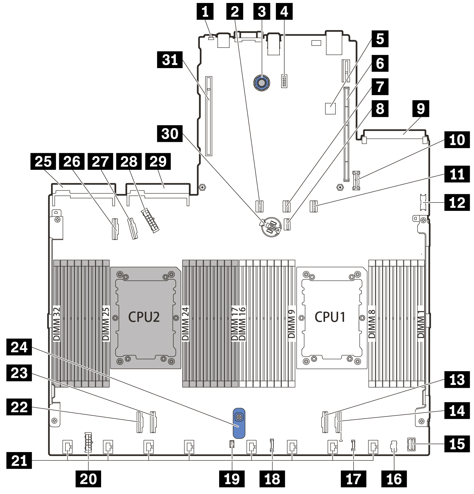
The illustration in this section shows the component locations on the system board.
Figure 1. System board components
| Callout | Callout |
|---|---|
| 1 NMI Button | 2 SATA Connector 0 |
| 3 System Board Release Pin | 4 Serial Port Module Connector |
| 5 Internal USB Connector | 6 Riser 1 Slot |
| 7 SATA Connector 1 | 8 7mm/M.2 Signal Connector |
| 9 OCP 3.0 Network Card Connector | 10 TPM Module Connector |
| 11 SATA 2/Rear Backplane Signal Connector | 12 Front USB Connector |
| 13 PCIe Connector 1 | 14 PCIe Connector 2 |
| 15 Front VGA Connector | 16 M.2 Power Connector |
| 17 External LCD Connector | 18 Front Panel Connector |
| 19 Intrusion Switch Connector | 20 Internal RAID Power Connector |
| 21 Fan 1-8 Connectors | 22 PCIe Connector 3 |
| 23 PCIe Connector 4 | 24 System Board Lift Handle |
| 25 Power Supply 1 Connector | 26 PCIe Connector 5 |
| 27 PCIe Connector 6 | 28 Front Backplane Power Connector |
| 29 Power Supply 2 Connector | 30 3V Battery (CR2032) |
| 31 Riser 2 slot |
Give documentation feedback