System-board-assembly connectors
The following illustrations show the internal connectors on the system board.
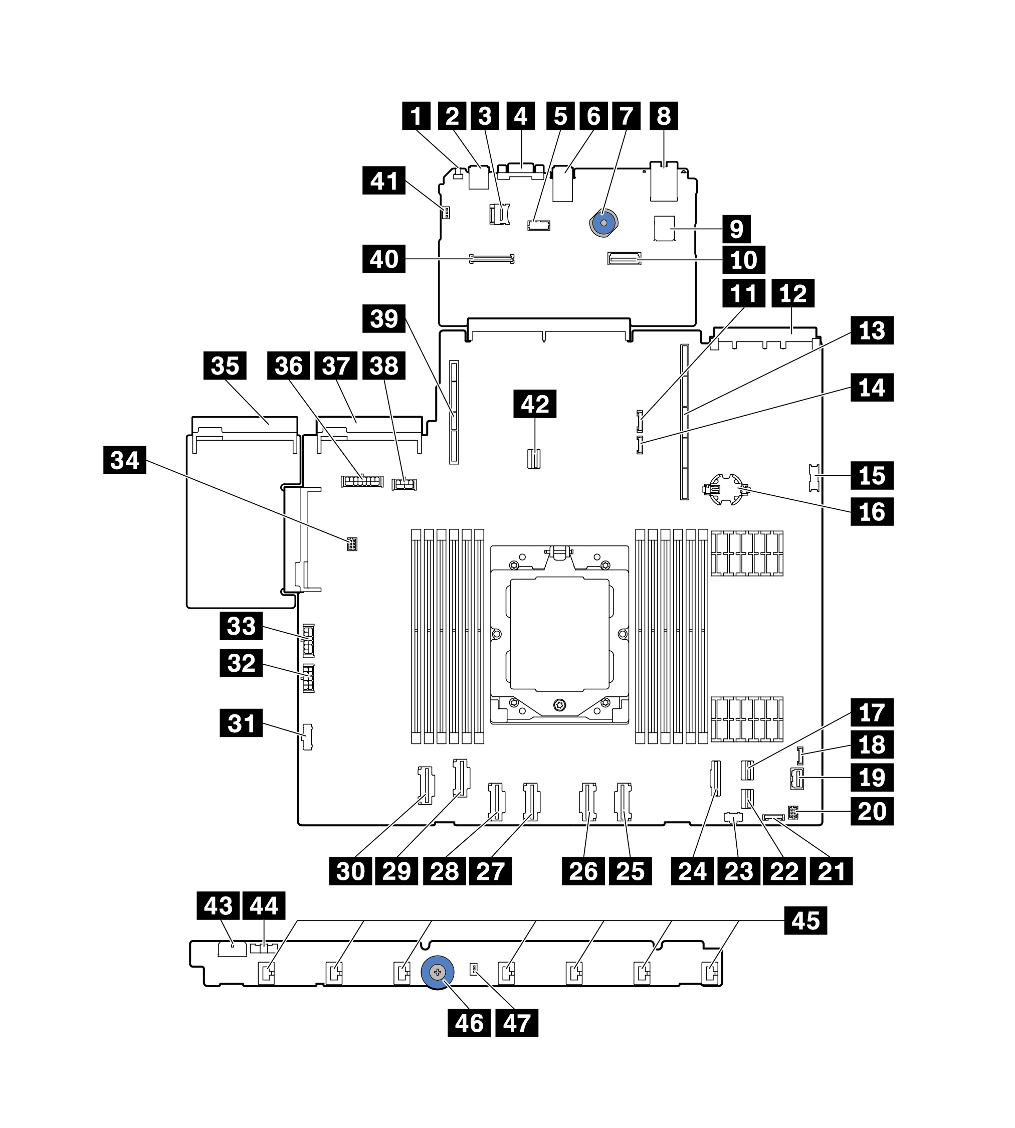
Figure 1. System-board-assembly connectors
| Callout | Callout |
|---|---|
| 1 NMI Button | 2 Rear USB Connector 1 |
| 3 MicroSD Connector | 4 VGA Connector |
| 5 Serial Port Connector | 6 Rear USB connector 2 |
| 7 Lift Handle | 8 MGMT NIC connector |
| 9 Internal USB Connector | 10 Second MGMT Ethernet Connector |
| 11 7mm/Rear BP Sideband Connector | 12 OCP 3.0 Network Card Connector |
| 13 Riser 1 Slot | 14 Leak Detection Connector |
| 15 Front USB Connector | 16 CMOS Battery(CR2032) |
| 17 PCIe Connector 8 / SATA Connector 1 | 18 External Diagnostics Connector |
| 19 Front VGA Connector | 20 Front I/O connector for Y cable |
| 21 Front Panel Connector | 22 PCIe Connector 9 / SATA Connector 2 |
| 23 M.2 Power Connector | 24 PCIe Connector 7 / SATA Connector 0 |
| 25 PCIe Connector 6 | 26 PCIe Connector 5 |
| 27 PCIe Connector 4 | 28 PCIe Connector 3 |
| 29 PCIe Connector 2 | 30 PCIe Connector 1 |
| 31 Fan Board Sideband Connector | 32 Fan Board Power Connector |
| 33 Internal RAID Power Connector | 34 Pump Connector |
| 35 Power Supply 1 Connector | 36 BP Power Connector note 1 |
| 37 Power Supply 2 Connector | 38 GPU/7mm/Rear BP Power Connectornote 2 |
| 39 Riser 2 Slot | 40 RoT Connector |
| 41 Intrusion Switch Connector (Reserved) | 42 M.2/7mm BP Signal Connector |
| 43 Fan Board Power Connector | 44 Fan Board Sideband Connector |
| 45 Fan 1-7 Connectors | 46 Lift Handle |
| 47 Intrusion Switch Connector |
Note
The silkscreen of this connector on the system board assembly may be either BP Pwr or BP1 Pwr.
The silkscreen of this connector on the system board assembly may be either 7MM/RBP/GPU Pwr or 7M/RBP/GPU Pwr.
Give documentation feedback