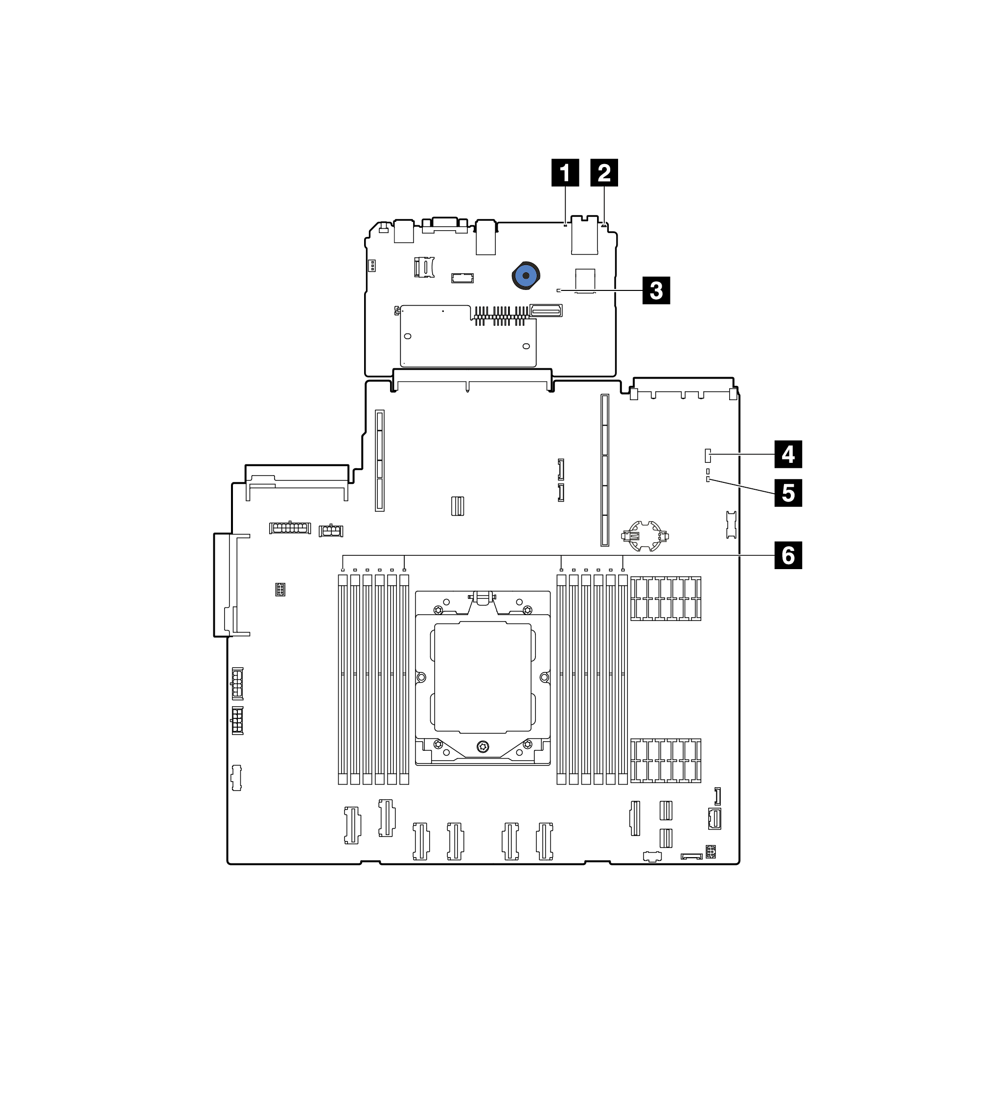
The following illustrations show the light-emitting diodes (LEDs) on the system board assembly which contains the system I/O board and the processor board.
Figure 1. System-board-assembly LEDs
1 System error LED (yellow)
2 System ID LED (blue)
3 XCC heartbeat LED (green)
4 System status LED (green)
5 FPGA heartbeat LED (green)
6 DIMM error LEDs (amber)
Table 1. System-board-assembly LEDs
LED
Description
Action
1 System error LED (yellow)
LED on: an error has occurred.
Check system logs or internal error LEDs to identify the failed part. For more information, see System error LED.
2 System ID LED (blue)
This LED helps you to visually locate the server.
A system ID button with LED is also located on the front of the server. You can press the system ID button to turn on/off or blink the front and rear ID LEDs.
3 XCC heartbeat LED (green)
The XCC heartbeat LED helps you identify the XCC status.
Blinking (1 Hz, about one flash per second) : XCC is working normally.
Blinking at other speeds or always on: XCC is at the initial phase or is working abnormally.
Off: XCC is not working.
If the XCC heartbeat LED is always off or always on, do the following:
If XCC cannot be accessed:
Re-plug the power cord.
Check and ensure that the system I/O board and the firmware and RoT security module are installed correctly. (Trained technician only) Reinstall them if needed.
(Trained technicians only) Replace the firmware and RoT security module.
(Trained technicians only) Replace the system I/O board.
If XCC can be accessed, replace the system I/O board.
If the XCC heartbeat LED is blinking fast over 5 minutes, do the following:
Re-plug the power cord.
Check and ensure that the system I/O board and the firmware and RoT security module are installed correctly. (Trained technician only) Reinstall them if needed.
(Trained technicians only) Replace the firmware and RoT security module.
(Trained technicians only) Replace the system I/O board.
If the XCC heartbeat LED is blinking slowly over 5 minutes, do the following:
Re-plug the power cord.
Check and ensure that the system I/O board and the firmware and RoT security module are installed correctly. (Trained technician only) Reinstall them if needed.
If the problem remains, contact Lenovo Support.
4 System status LED (green)
The system status LED indicates the working status of the system.
Fast blinking (about four flashes per second): Power fault or is waiting for XCC power permission ready.
Slow blinking (about one flash per second): Power off and is ready to be powered on (standby state).
ON: Power on
Video of LED blinking status is available at: YouTube
If the system status LED is blinking fast over 5 minutes and cannot power on, check the XCC heartbeat LED and follow the actions for the XCC heartbeat LED.
If the system status LED remains off or is blinking fast (about four flashes per second) and the system error LED on the front panel is on (yellow), the system is in a power fault status. Do the following:
Re-plug the power cord.
Remove installed adapters/devices, one at a time, until you reach the minimal configuration for debugging.
(Trained technicians only) If the problem remains, capture FFDC log, and replace the processor board.
If the problem still remains, contact Lenovo Support.
5 FPGA heartbeat LED (green)
The FPGA heartbeat LED helps you identify the FPGA status.
Blinking (about one flash per second): FPGA is working normally.
On or off: FPGA is not working.
If the FPGA heartbeat LED is always off or always on, do the following:
Replace the processor board.
If the problem remains, contact Lenovo Support.
6 DIMM error LEDs (Amber)
LED on: an error has occurred to the DIMM the LED represents.