Front operator panel LEDs
The front operator panel of the server provides controls, connectors, and LEDs.
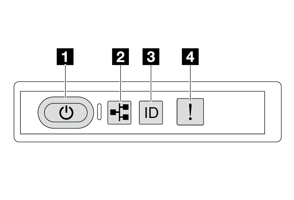
| 1 Power button with power status LED (green) | 3 System ID button with system ID LED (blue) |
| 2 Network activity LED (green) | 4 System Error LED (yellow) |
1 Power button with power status LED (green)
You can press the power button to power on the server when you finish setting up the server. You also can hold the power button for several seconds to power off the server if you cannot shut down the server from the operating system. The states of the power LED are as follows:
| Status | Color | Description |
|---|---|---|
| Off | None | No power supply is properly installed, or the LED itself has failed. |
| Flashing rapidly (four times per second) | Green | The server is turned off and is not ready to be turned on. The power button is disabled. This will last approximately 5 to 10 seconds. |
| Flashing slowly (once per second) | Green | The server is turned off and is ready to be turned on. You can press the power button to turn on the server. |
| Lit | Green | The server is turned on. |
2 Network activity LED (green)
The network activity LED helps you identify the network connectivity and activity.
| Status | Color | Description |
|---|---|---|
| On | Green | The server is connected to a network. |
| Blinking | Green | The network is connected and active. |
| Off | None | The server is disconnected from the network. |
3 System ID button with system ID LED (blue)
Use this system ID button and the blue system ID LED to visually locate the server. Each time you press the system ID button, the state of the system ID LED changes. The LED can be changed to on, blinking, or off. You can also use the Lenovo XClarity Controller or a remote management program to change the state of the system ID LED to assist in visually locating the server among other servers.
If the XClarity Controller USB connector is set to have both the USB 2.0 function and XClarity Controller management function, you can press the system ID button for three seconds to switch between the two functions.
4 System Error LED (yellow)
The system error LED provides basic diagnostic functions for your server. If the system error LED is lit, one or more LEDs elsewhere in the server might also be lit to direct you to the source of the error.
| Status | Color | Description | Action |
|---|---|---|---|
| On | Yellow | An error has been detected on the server. Causes might include but are not limited to the following errors:
|
|
| Off | None | The server is off, or the server is on and is working correctly. | None. |