Rear view
The rear view of the server varies by model. Depending on the model, your server might look slightly different from the illustrations in this topic.
Refer to the following rear view for different server models:
Server model with three PCIe slots
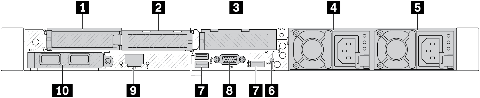
| 1 PCIe slot 1 on riser 1 assembly | 2 PCIe slot 2 on riser 1 assembly |
| 3 PCIe slot 3 on riser 2 assembly | 4 Power supply 2 (optional) |
| 5 Power supply 1 | 6 NMI button |
| 7 USB 3.2 Gen 1 (5 Gbps) connectors (3 DCIs) | 8 VGA connector |
| 9 XClarity Controller network connector | 10 Ethernet connectors on OCP 3.0 Ethernet adapter (optional) |
Server model with two PCIe slots
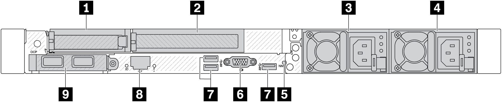
| 1 PCIe slot 1 on riser 1 assembly | 2 PCIe slot 2 on riser 1 assembly |
| 3 Power supply 2 (optional) | 4 Power supply 1 |
| 5 NMI button | 6 VGA connector |
| 7 USB 3.2 Gen 1 (5 Gbps) connectors (3 DCIs) | 8 XClarity Controller network connector |
| 9 Ethernet connectors on OCP 3.0 Ethernet adapter (optional, two or four connectors may be available) |
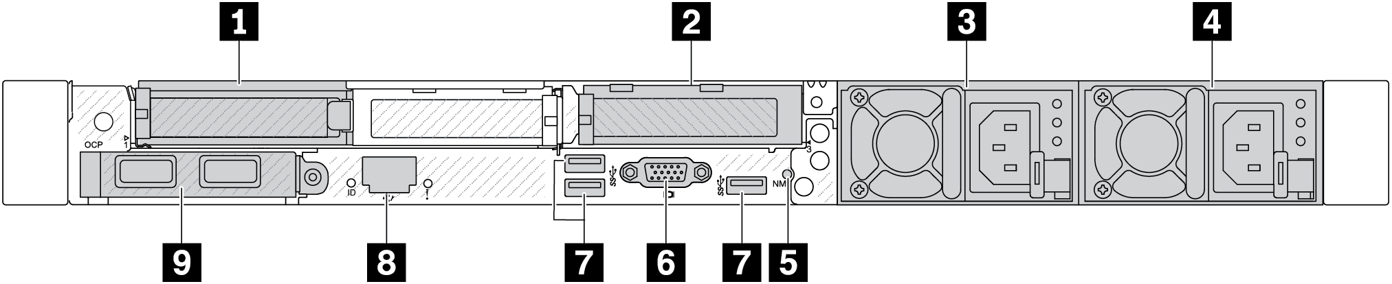
| 1 PCIe slot 1 on riser 1 assembly | 2 PCIe slot 3 on riser 2 assembly |
| 3 Power supply 2 (optional) | 4 Power supply 1 |
| 5 NMI button | 6 VGA connector |
| 7 USB 3.2 Gen 1 (5 Gbps) connectors (3 DCIs) | 8 XClarity Controller network connector |
| 9 Ethernet connectors on OCP 3.0 Ethernet adapter (optional, two or four connectors may be available) |
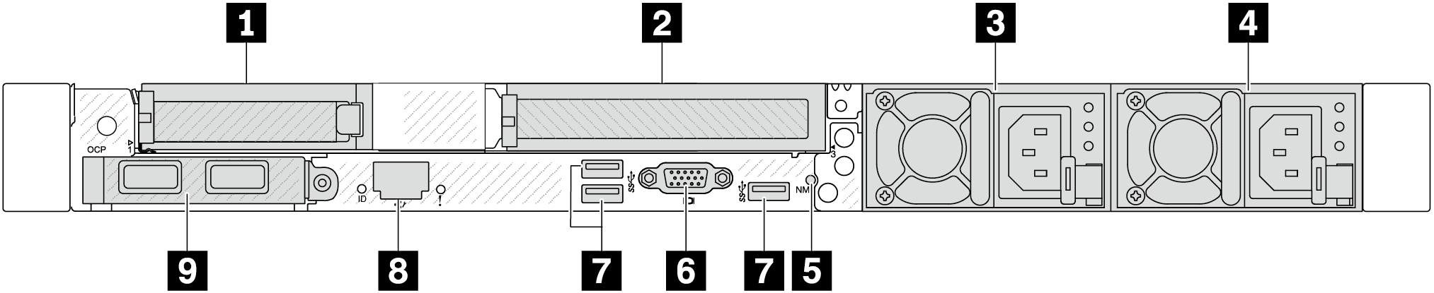
| 1 PCIe slot 1 on riser 1 assembly | 2 PCIe slot 3 on riser 2 assembly |
| 3 Power supply 2 (optional) | 4 Power supply 1 |
| 5 NMI button | 6 VGA connector |
| 7 USB 3.2 Gen 1 (5 Gbps) connectors (3 DCIs) | 8 XClarity Controller network connector |
| 9 Ethernet connectors on OCP 3.0 Ethernet adapter (optional, two or four connectors may be available) |
Server model with two 2.5'' hot-swap rear drive bays and one PCIe slot
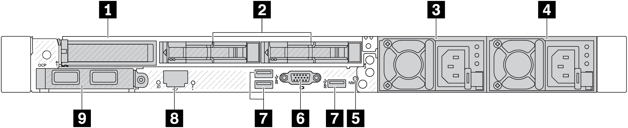
| 1 PCIe slot 1 on riser 1 assembly | 2 Rear 2.5'' drive bays (2) |
| 3 Power supply 2 (optional) | 4 Power supply 1 |
| 5 NMI button | 6 VGA connector |
| 7 USB 3.2 Gen 1 (5 Gbps) connectors (3 DCIs) | 8 XClarity Controller network connector |
| 9 Ethernet connectors on OCP 3.0 Ethernet adapter (optional, two or four connectors may be available) |
Server model with two 7mm hot-swap rear drive bays and two PCIe slots
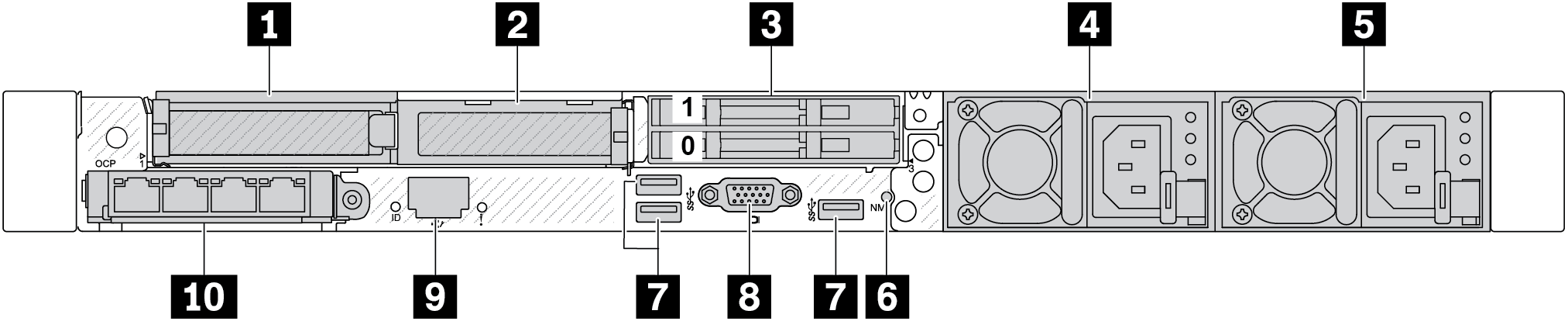
| 1 PCIe slot 1 on riser 1 assembly | 2 PCIe slot 2 on riser 1 assembly |
| 3 Rear 7mm drive bays (2) | 4 Power supply 2 (optional) |
| 5 Power supply 1 | 6 NMI button |
| 7 USB 3.2 Gen 1 (5 Gbps) connectors (3 DCIs) | 8 VGA connector |
| 9 XClarity Controller network connector | 10 Ethernet connectors on OCP 3.0 Ethernet adapter (optional, two or four connectors may be available) |
Server model with two 7mm hot-swap rear drive bays and one PCIe slot
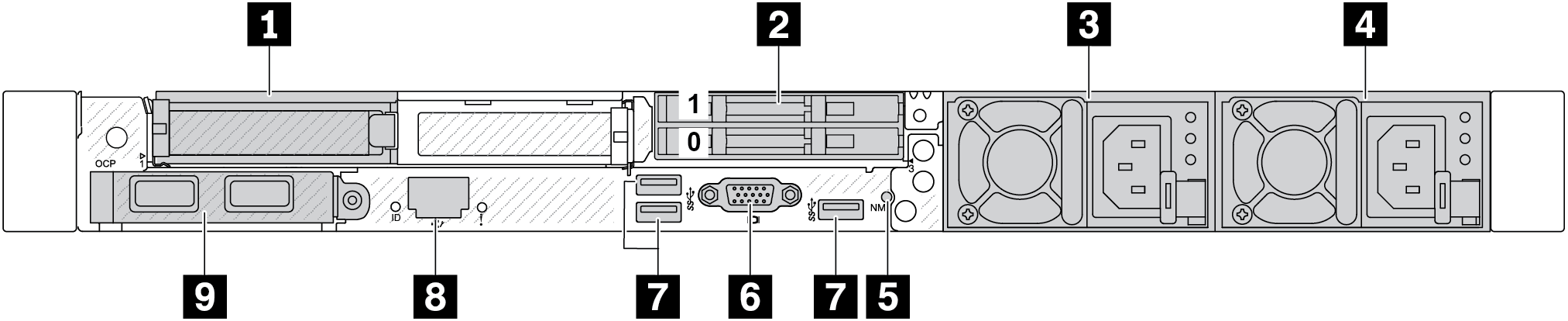
| 1 PCIe slot 1 on riser 1 assembly | 2 Rear 7mm drive bays (2) |
| 3 Power supply 2 (optional) | 4 Power supply 1 |
| 5 NMI button | 6 VGA connector |
| 7 USB 3.2 Gen 1 (5 Gbps) connectors (3 DCIs) | 8 XClarity Controller network connector |
| 9 Ethernet connectors on OCP 3.0 Ethernet adapter (optional, two or four connectors may be available) |
Server model with two PCIe slots and a direct water cooling module
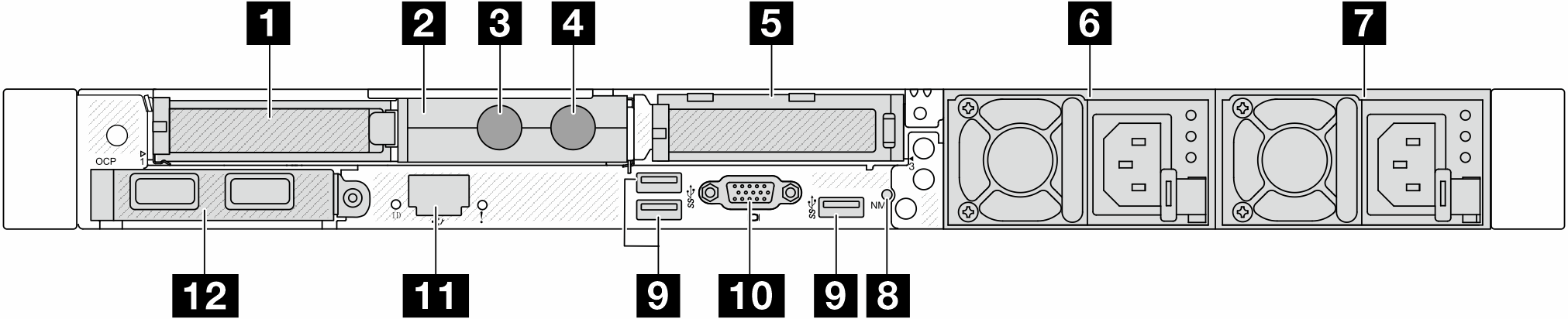
| 1 PCIe slot 1 on riser 1 assembly | 2 Hose holder |
| 3 Inlet hose | 4 Outlet hose |
| 5 PCIe slot 3 on riser 2 assembly | 6 Power supply 2 (optional) |
| 7 Power supply 1 | 8 NMI button |
| 9 USB 3.2 Gen 1 (5Gbps) connectors (3 DCIs) | 10 VGA connector |
| 11 XClarity Controller network connector | 12 Ethernet connectors on OCP module (optional, two or four connectors may be available) |
Rear components overview
OCP 3.0 module
Figure 5. OCP module (two connectors) 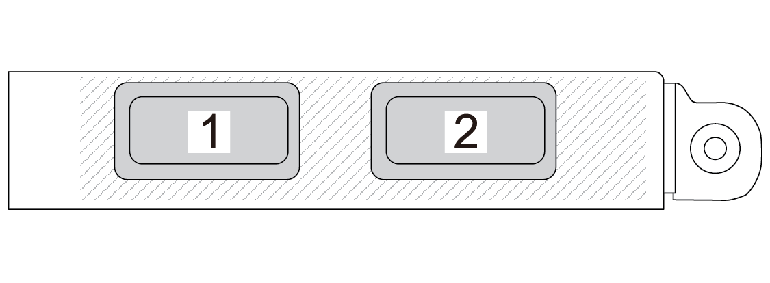 | Figure 6. OCP module (four connectors) 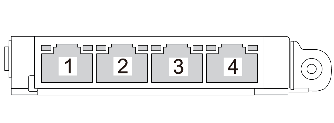 |
The OCP module provides two or four extra Ethernet connectors for network connections.
By default, any Ethernet connector on the OCP module can also function as a management connector using the shared management capacity.
The OCP module provides two or four extra Ethernet connectors for network connections.
By default, any of the connectors on the OCP module can function as a shared management connector.
Hot-swap drives and drive bays
The drive bays on the front and rear of your server are designed for hot-swap drives. The number of the installed drives in your server varies by model. When you install drives, follow the order of the drive bay numbers.
The EMI integrity and cooling of the server are protected by having all drive bays occupied. Vacant drive bays must be occupied by drive fillers.
PCIe slots
The PCIe slots are on the rear of the server and your server supports up to three PCIe slots on riser 1 and 2 assemblies.
Power supply units
The hot-swap redundant power supply helps you avoid significant interruption to the operation of the system when a power supply fails. You can purchase a power supply option from Lenovo and install the power supply to provide power redundancy without turning off the server.
On each power supply, there are three status LEDs near the power cord connector. For information about the LEDs, see Troubleshooting by system LEDs and diagnostics display.
USB 3.2 Gen1 (5 Gbps) connectors
The USB 3.2 Gen1 (5 Gbps) connectors are direct connect interfaces (DCIs) for debugging, which can be used to attach a USB-compatible device, such as a USB keyboard, USB mouse, or USB storage device.
VGA connector
The VGA connectors on the front and rear of the server can be used to attach a high-performance monitor, a direct-drive monitor, or other devices that use a VGA connector.
XCC system management port (10/100/1000 Mbps RJ-45)
The XCC system management port (10/100/1000 Mbps RJ-45) can be used to attach an Ethernet cable to manage the baseboard management controller (BMC).