Front view
The front view of the server varies by model. Depending on the model, your server might look slightly different from the illustrations in this topic.
Server model with four 2.5'' drive bays
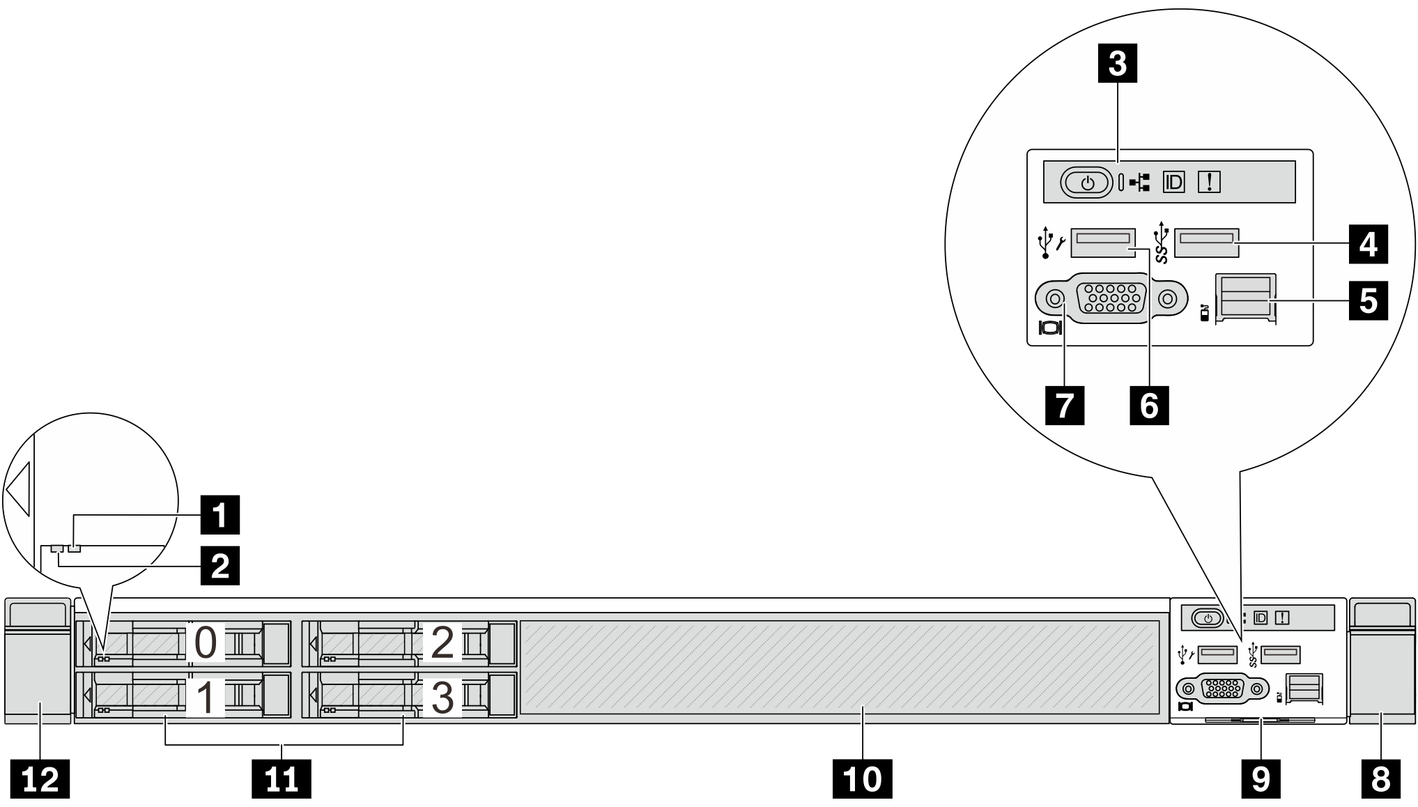
| 1 Drive status LED | 2 Drive activity LED |
| 3 Diagnostics panel | 4 USB 3.2 Gen 1 (5Gbps) connector |
| 5 External LCD connector | 6 XClarity Controller USB connector |
| 7 VGA connector (optional) | 8 Rack latch (right) |
| 9 Pull-out information tab | 10 Drive filler (1) |
| 11 Drive bays (4) | 12 Rack latch (left) |
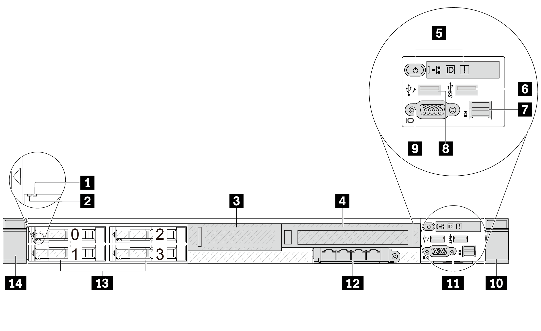
Server model with four 2.5-inch drive bays and a front riser assembly
| 1 Drive status LED | 2 Drive activity LED |
| 3 Font low-profile PCIe (riser 3, slot 4) | 4 Front full-height PCIe (riser 4, slot 5) |
| 5 Diagnostics panel | 6 USB 3.2 Gen 1 (5Gbps) connector |
| 7 External LCD connector | 8 XClarity Controller USB connector |
| 9 VGA connector (optional) | 10 Rack latch (right) |
| 11 Pull-out information tab | 12 Front OCP module |
| 13 Drive bays (4) | 14 Rack latch (left) |
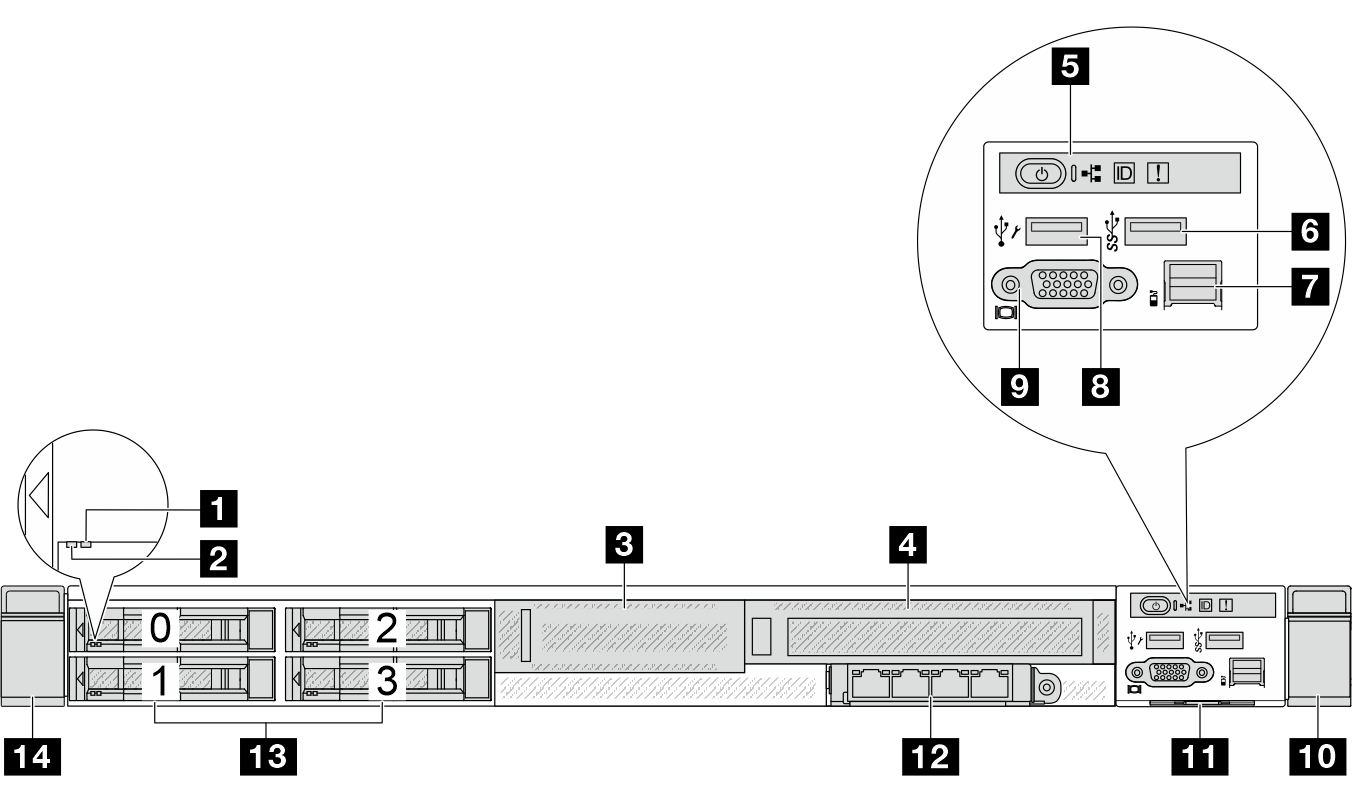
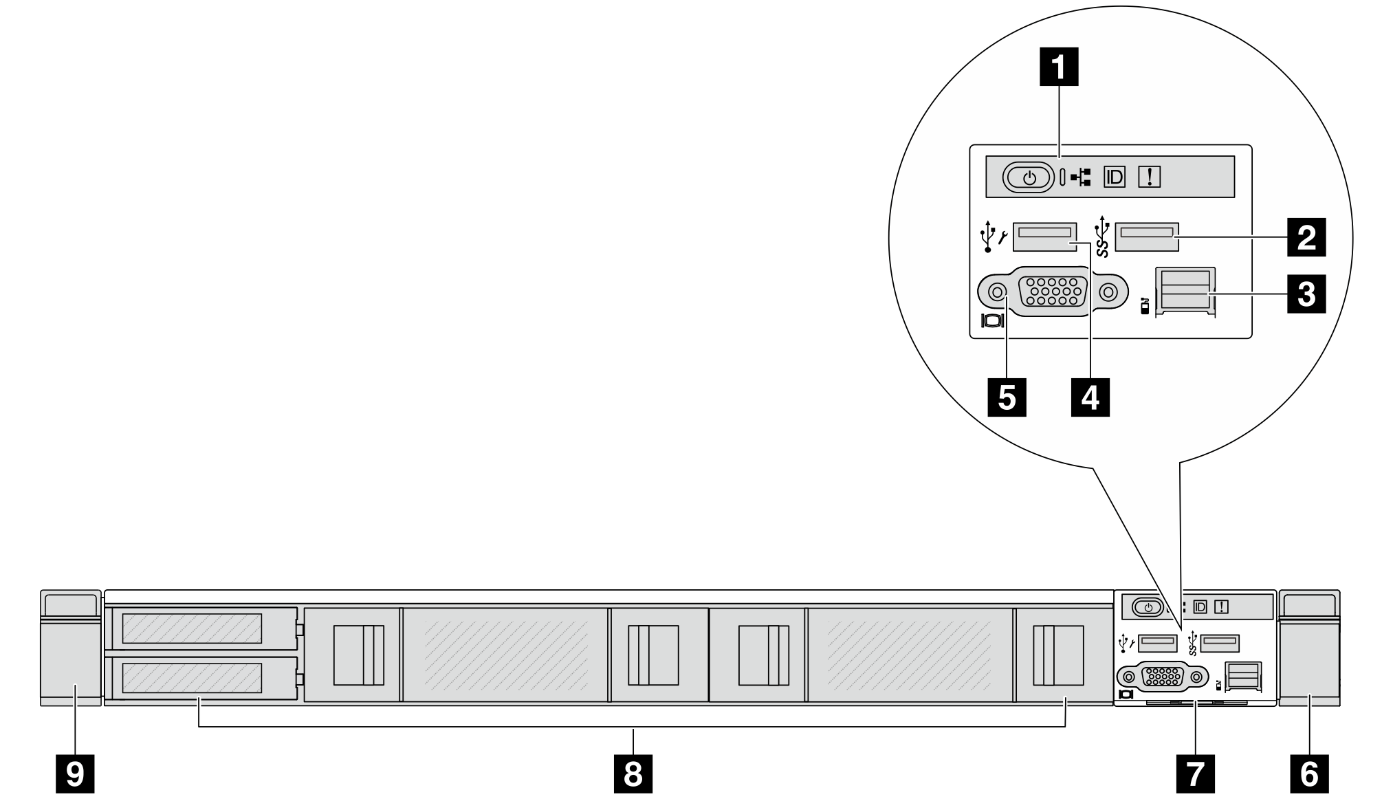
Server model with four 2.5'' AnyBay drive bays
| 1 Drive status LED | 2 Drive activity LED |
| 3 Low-profile riser bracket | 4 Full-height riser bracket |
| 5 Diagnostics panel | 6 USB 3.2 Gen 1 (5 Gbps) connector |
| 7 External diagnostics connector | 8 XClarity Controller USB connector |
| 9 VGA connector (optional) | 10 Rack latch (right) |
| 11 Pull-out information tab | 12 OCP 3.0 connectors |
| 13 Drive bays (4) | 14 Rack latch (left) |
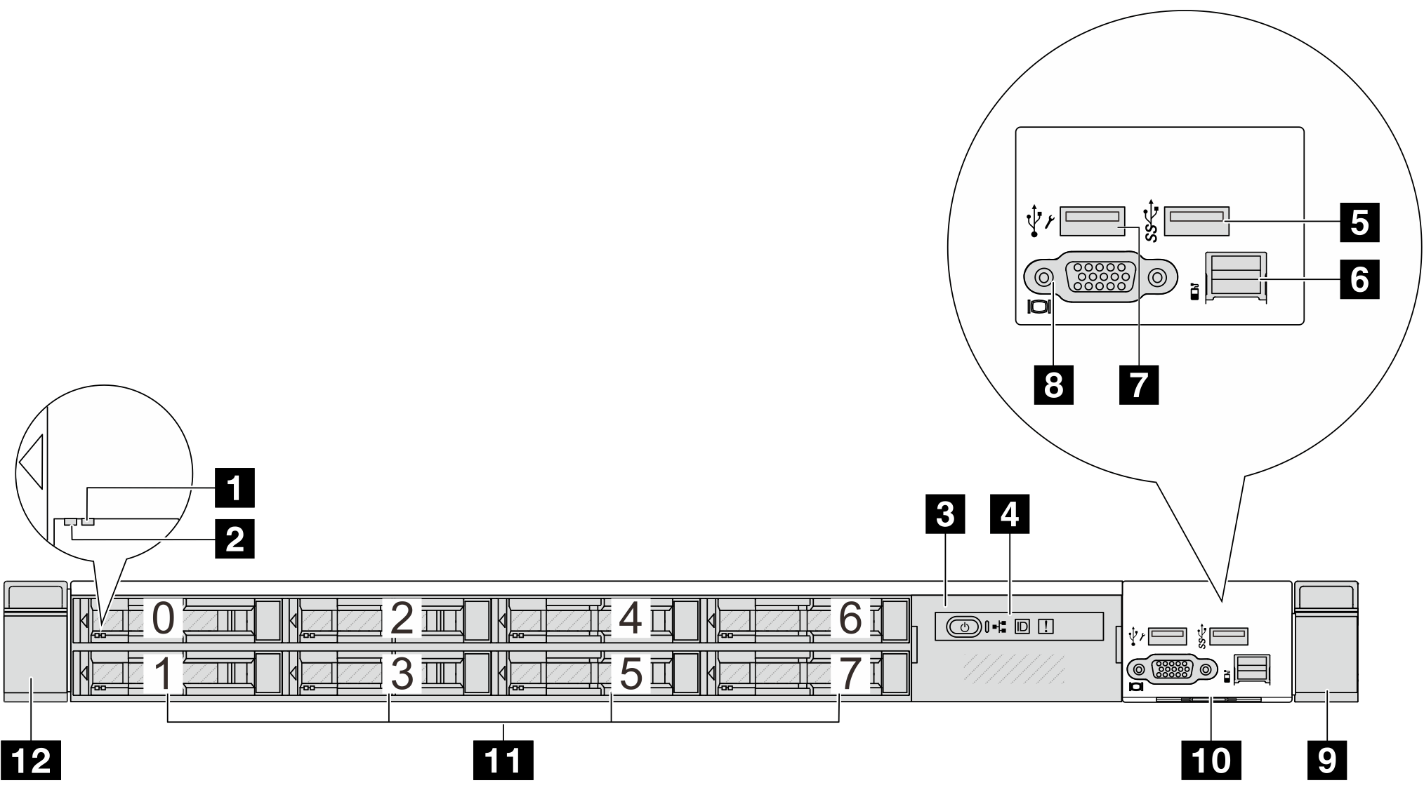
Server model with eight 2.5'' drive bays
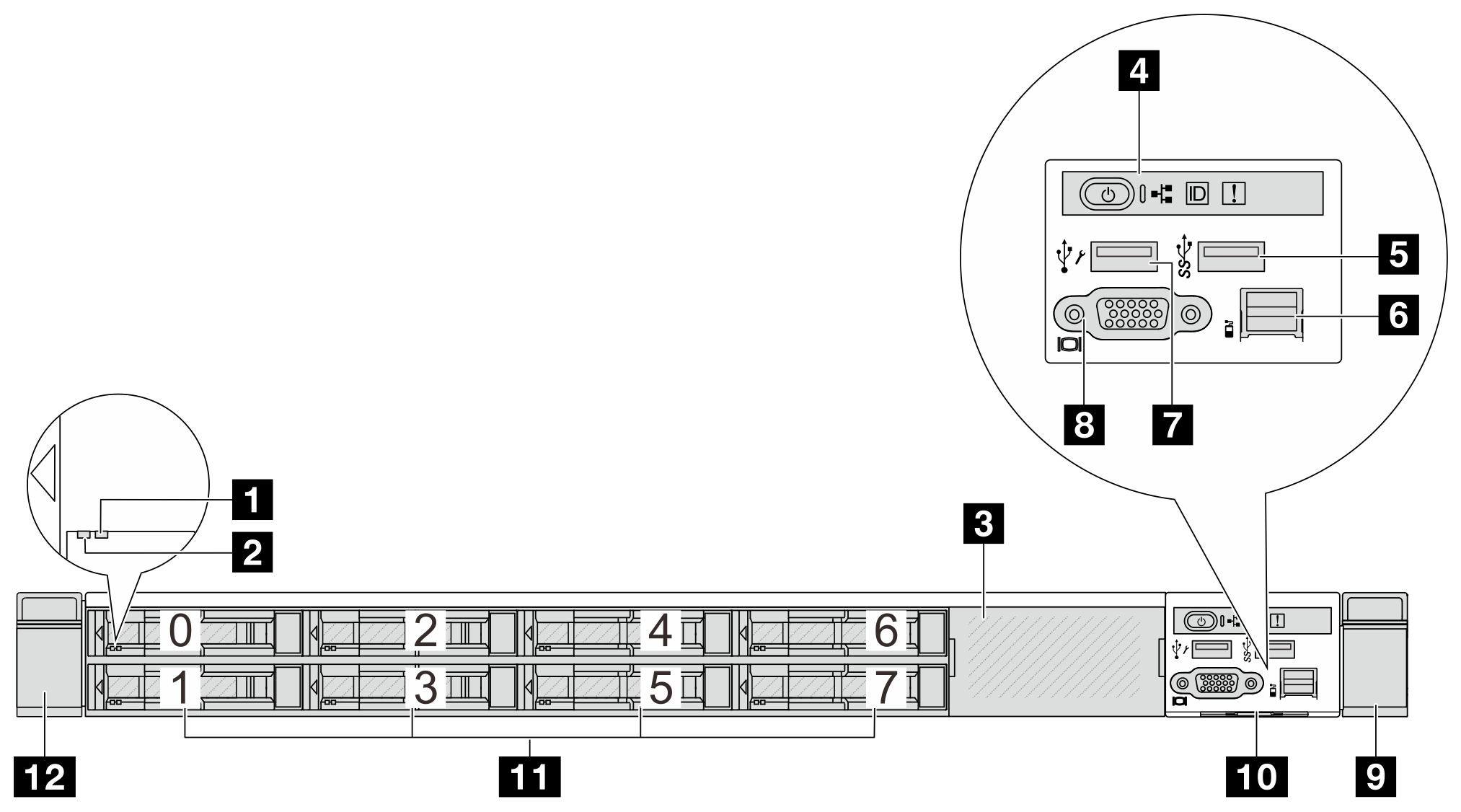
| 1 Drive status LED | 2 Drive activity LED |
| 3 Drive filler (1) | 4 Diagnostics panel |
| 5 USB 3.2 Gen 1 (5Gbps) connector | 6 External LCD connector |
| 7 XClarity Controller USB connector | 8 VGA connector (optional) |
| 9 Rack latch (right) | 10 Pull-out information tab |
| 11 Drive bays (8) | 12 Rack latch (left) |
Server model with ten 2.5'' drive bays
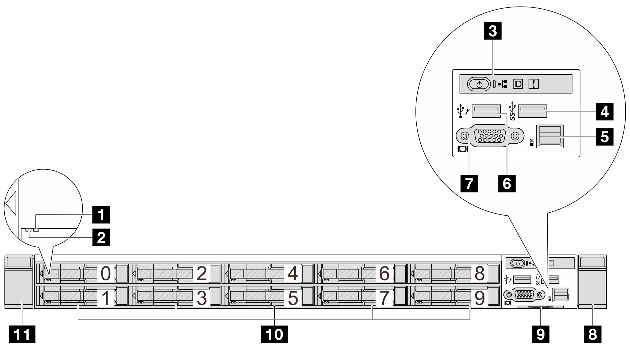
| 1 Drive status LED | 2 Drive activity LED |
| 3 Diagnostics panel | 4 USB 3.2 Gen 1 (5Gbps) connector |
| 5 External LCD connector | 6 XClarity Controller USB connector |
| 7 VGA connector (optional) | 8 Rack latch (right) |
| 9 Pull-out information tab | 10 Drive bays (10) |
| 11 Rack latch (left) |
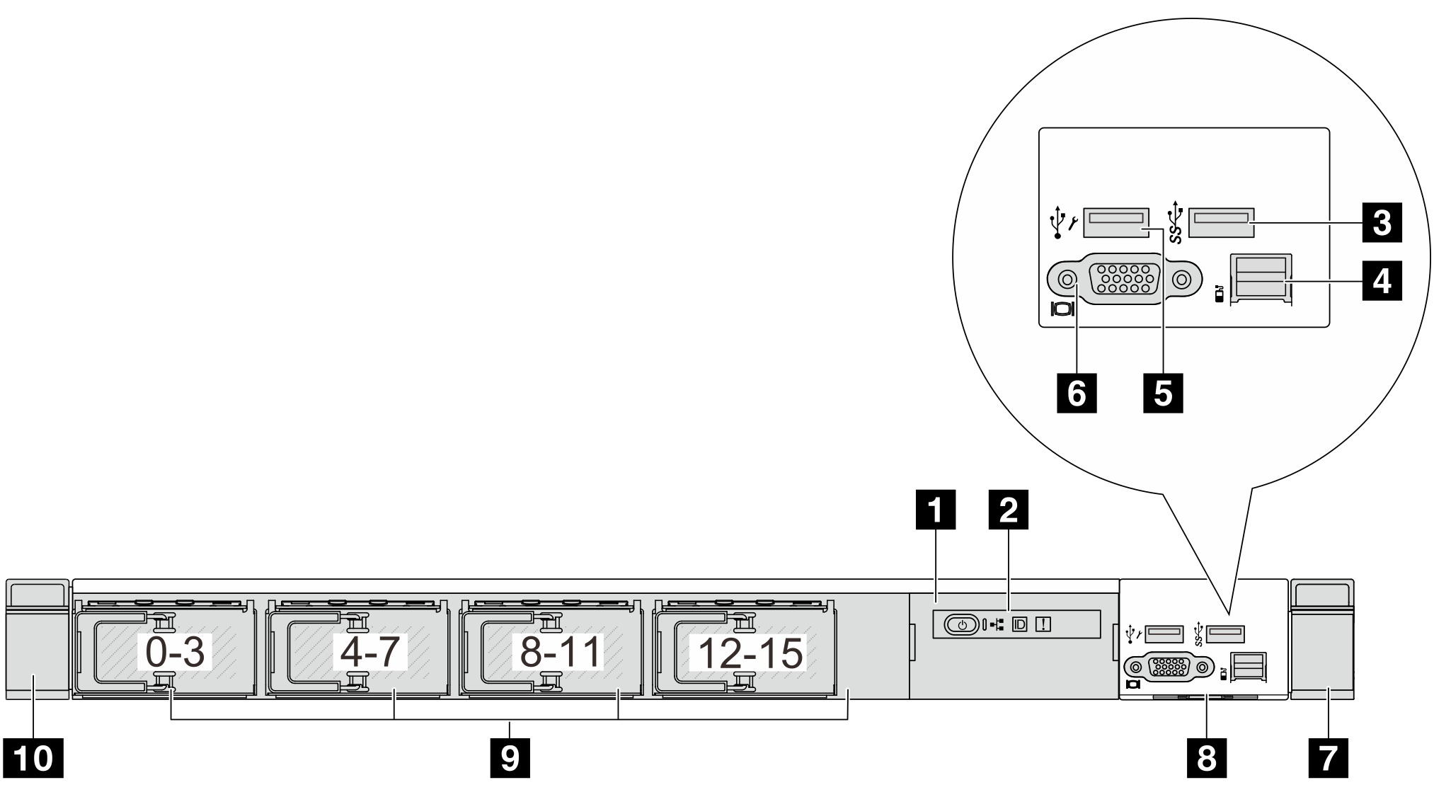
Server model with 16 EDSFF drives
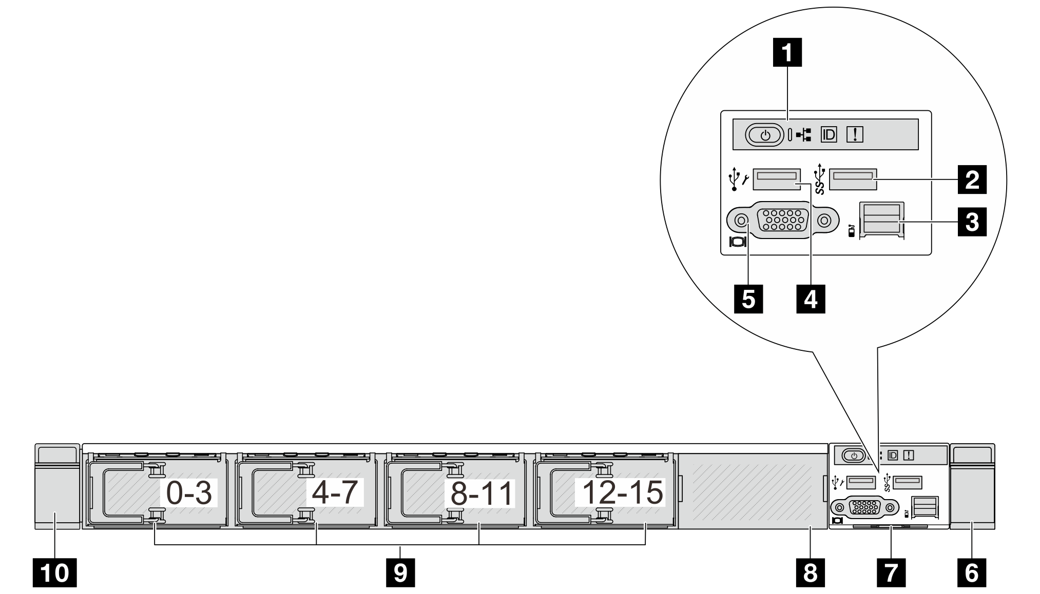
| 1 Diagnostics panel | 2 USB 3.2 Gen 1 (5Gbps) connector |
| 3 External LCD connector | 4 XClarity Controller USB connector |
| 5 VGA connector (optional) | 6 Rack latch (right) |
| 7 Pull-out information tab | 8 Drive filler (1) |
| 9 Drive bays (16) | 10 Rack latch (left) |
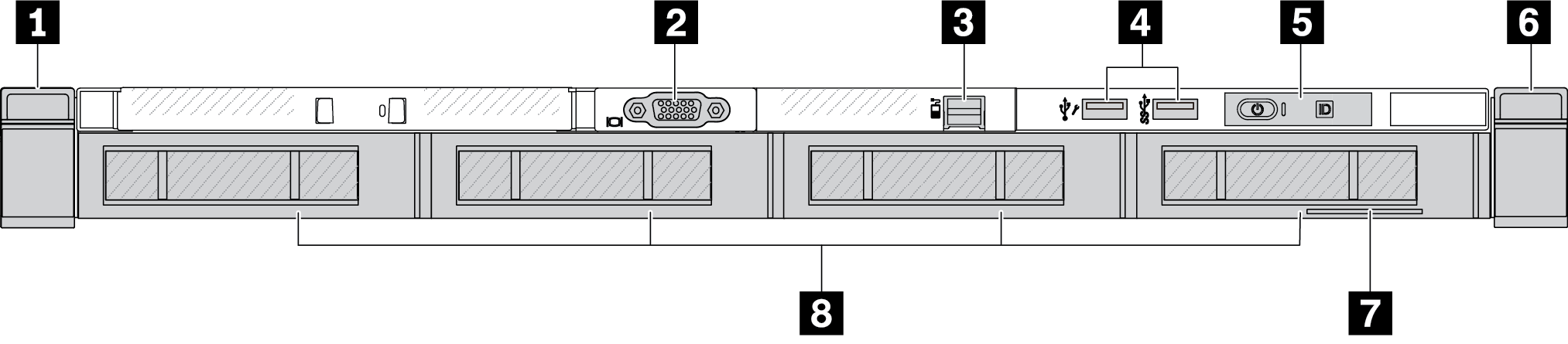
Server model with four 3.5'' drive bays
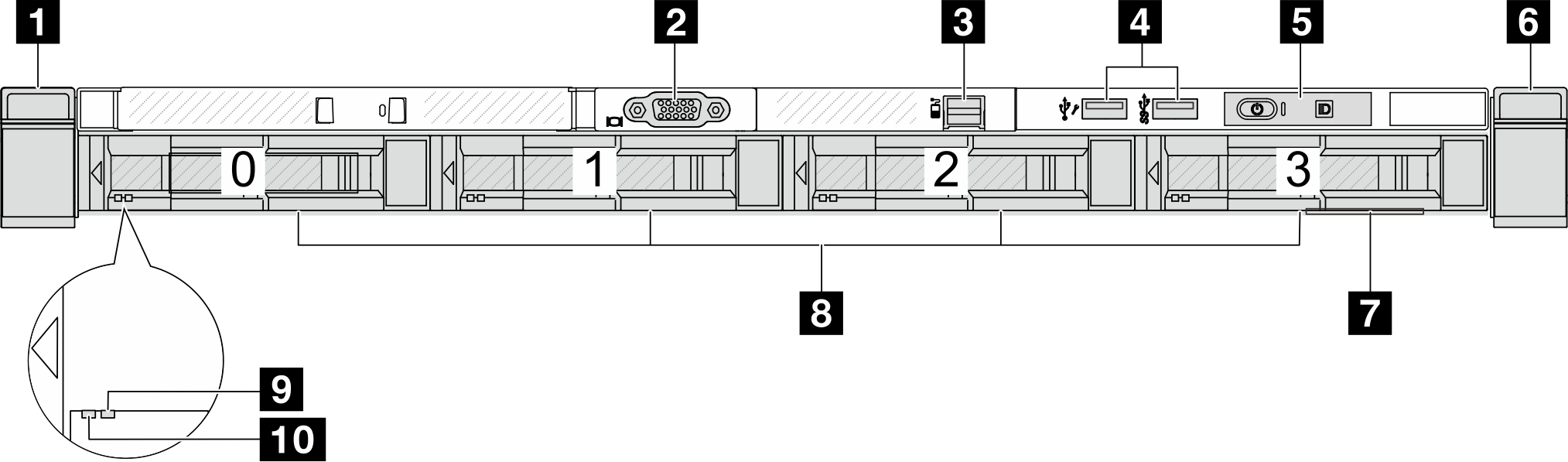
| 1 Rack latch (left) | 2 VGA connector (optional) |
| 3 External LCD connector | 4 XClarity Controller USB connector and USB 3.2 Gen 1 (5Gbps) connector |
| 5 Diagnostics panel | 6 Rack latch (right) |
| 7 Pull-out information tab | 8 Drive bays (4) |
| 9 Drive status LED | 10 Drive activity LED |
Server model with 2.5'' drive bays (backplane-less)
| 1 Diagnostics panel | 2 USB 3.2 Gen 1 (5Gbps) connector |
| 3 External LCD connector (reserved) | 4 XClarity Controller USB connector |
| 5 VGA connector (optional) | 6 Rack latch (right) |
| 7 Pull-out information tab | 8 Drive fillers (4) |
| 9 Rack latch (left) |
Server model with 3.5'' drive bays (backplane-less)
| 1 Rack latch (left) | 2 VGA connector (optional) |
| 3 External LCD connector | 4 XClarity Controller USB connector and USB 3.2 Gen 1 (5Gbps) connector |
| 5 Diagnostics panel | 6 Rack latch (right) |
| 7 Pull-out information tab | 8 Drive fillers (4) |
Server model with eight 2.5'' drive bays (with external diagnostics panel assembly)
| 1 Drive status LED | 2 Drive activity LED |
| 3 External diagnostics panel assembly | 4 External diagnostics panel |
| 5 USB 3.2 Gen 1 (5Gbps) connector | 6 External diagnostics connector |
| 7 XClarity Controller USB connector | 8 VGA connector (optional) |
| 9 Rack latch (right) | 10 Pull-out information tab |
| 11 Drive bays (8) | 12 Rack latch (left) |
Server model with 16 EDSFF drives (with external diagnostics panel assembly)
| 1 LCD diagnostics panel assembly | 2 External diagnostics panel |
| 3 USB 3.2 Gen 1 (5Gbps) connector | 4 External diagnostics connector |
| 5 XClarity Controller USB connector | 6 VGA connector (optional) |
| 7 Rack latch (right) | 8 Pull-out information tab |
| 9 Drive bays (16) | 10 Rack latch (left) |
Front components overview
Integrated Diagnostics Panel
The diagnostics panel is integrated in front I/O assembly on some models. For information about the controls and status LEDs on the diagnostics panel, see Integrated diagnostics panel.
External diagnostics port
The connector is for connecting an external diagnostics handset. For more about its functions, see External diagnostics handset.
Front operator panel
The assembly comes with an integrated diagnostics panel that can be used to quickly obtain system status, firmware levels, network information, and health information about the system. For more about the panel functions, see Front operator panel.
Hot-swap drives and drive bays
The drive bays on the front and rear of your server are designed for hot-swap drives. The number of the installed drives in your server varies by model. When you install drives, follow the order of the drive bay numbers.
The EMI integrity and cooling of the server are protected by having all drive bays occupied. Vacant drive bays must be occupied by drive fillers.
Pull-out information tab
The Lenovo XClarity Controller network access label is attached on the pull-out information tab. The default Lenovo XClarity Controller hostname and the IPv6 Link Local Address (LLA) are provided on the tab.
For more information, see Set the network connection for the Lenovo XClarity Controller.
Rack latches
If your server is installed in a rack, you can use the rack latches to help you slide the server out of the rack. You also can use the rack latches and screws to secure the server in the rack so that the server cannot slide out, especially in vibration-prone areas. For more information, refer to the Rack Installation Guide that comes with your rail kit.
USB 3.2 Gen1 (5 Gbps) connectors
The USB 3.2 Gen1 (5 Gbps) connectors can be used to attach a USB-compatible device, such as a USB keyboard, USB mouse, or USB storage device.
VGA connector
The VGA connectors on the front and rear of the server can be used to attach a high-performance monitor, a direct-drive monitor, or other devices that use a VGA connector.
XClarity Controller USB connector
The XClarity Controller USB connector can function as a regular USB 2.0 connector to the host OS. In addition, it can also be used to connect the server to an android or iOS device, where you can then install and launch the Lenovo XClarity Mobile app to manage the system using XClarity Controller.
For details about using the Lenovo XClarity Mobile app, refer to Lenovo XClarity Administrator Mobile app online documentation.
OCP 3.0 module
Figure 1. OCP module (two connectors) 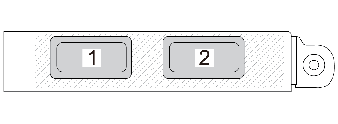 | Figure 2. OCP module (four connectors) 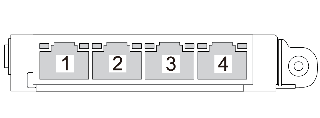 |
The OCP module provides two or four extra Ethernet connectors for network connections.
By default, any Ethernet connector on the OCP module can also function as a management connector using the shared management capacity.