Install the 4 x 3.5" drive backplane and drive cage
Use this information to install 3.5-inch 4-bay drive backplane and drive cage.
About this task
Read Installation Guidelines and Safety inspection checklist to ensure that you work safely.
Power off the server and peripheral devices and disconnect the power cords and all external cables. See Power off the server.
Prevent exposure to static electricity, which might lead to system halt and loss of data, by keeping static-sensitive components in their static-protective packages until installation, and handling these devices with an electrostatic-discharge wrist strap or other grounding system.
The rear drive cage is supported on some server models with thermal requirements. See Thermal rules to ensure that the server is under permitted ambient temperature and the correct heat sink and system fans are used. If needed, replace your heat sink or system fan first.
Procedure
- Install the drive backplane into the rear drive cage.Figure 1. Installing the 4 x 3.5-inch rear drive backplane
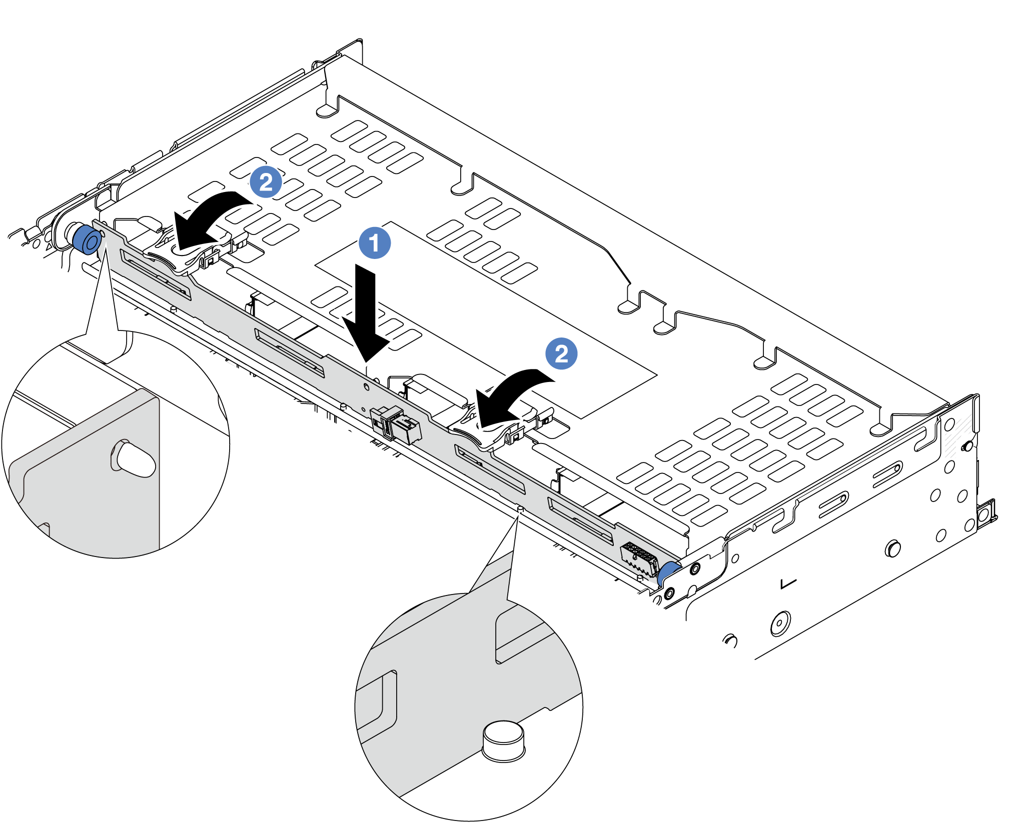
 Align the bottom of the backplane with the studs at the bottom of the drive cage and lower the backplane into the drive cage.
  Push the top of the backplane so that the holes in the backplane pass through the pins on the drive cage, and the release latches secure the backplane in place.
- Install the rear drive cage.Figure 2. Installing the 4 x 3.5-inch rear drive cage
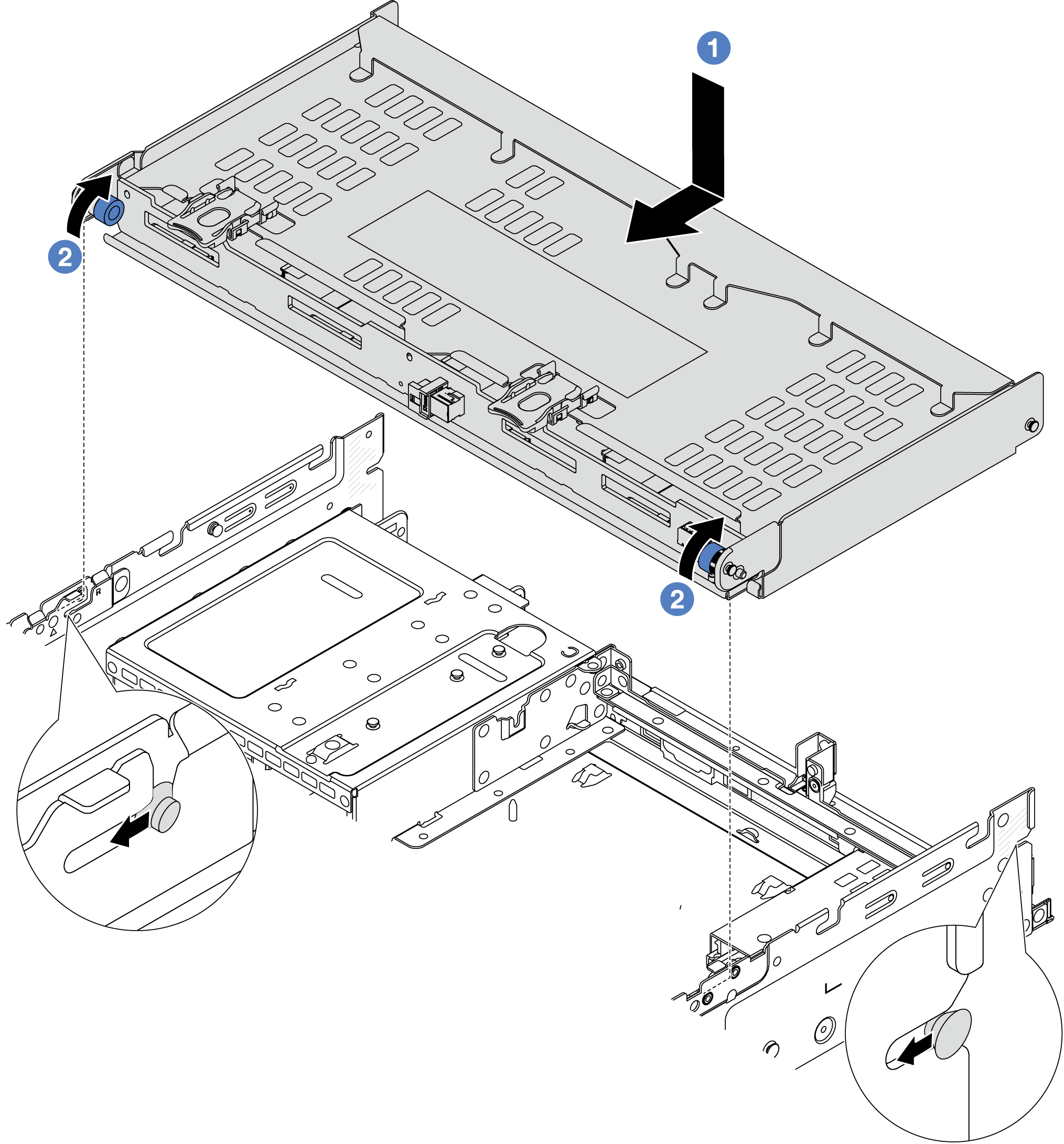
- Align the rear drive cage with the chassis, and lower the drive cage into the chassis. Move the rear drive cage forward until it clicks into position.
- Twist and release the blue plunger to secure the drive cage in place.
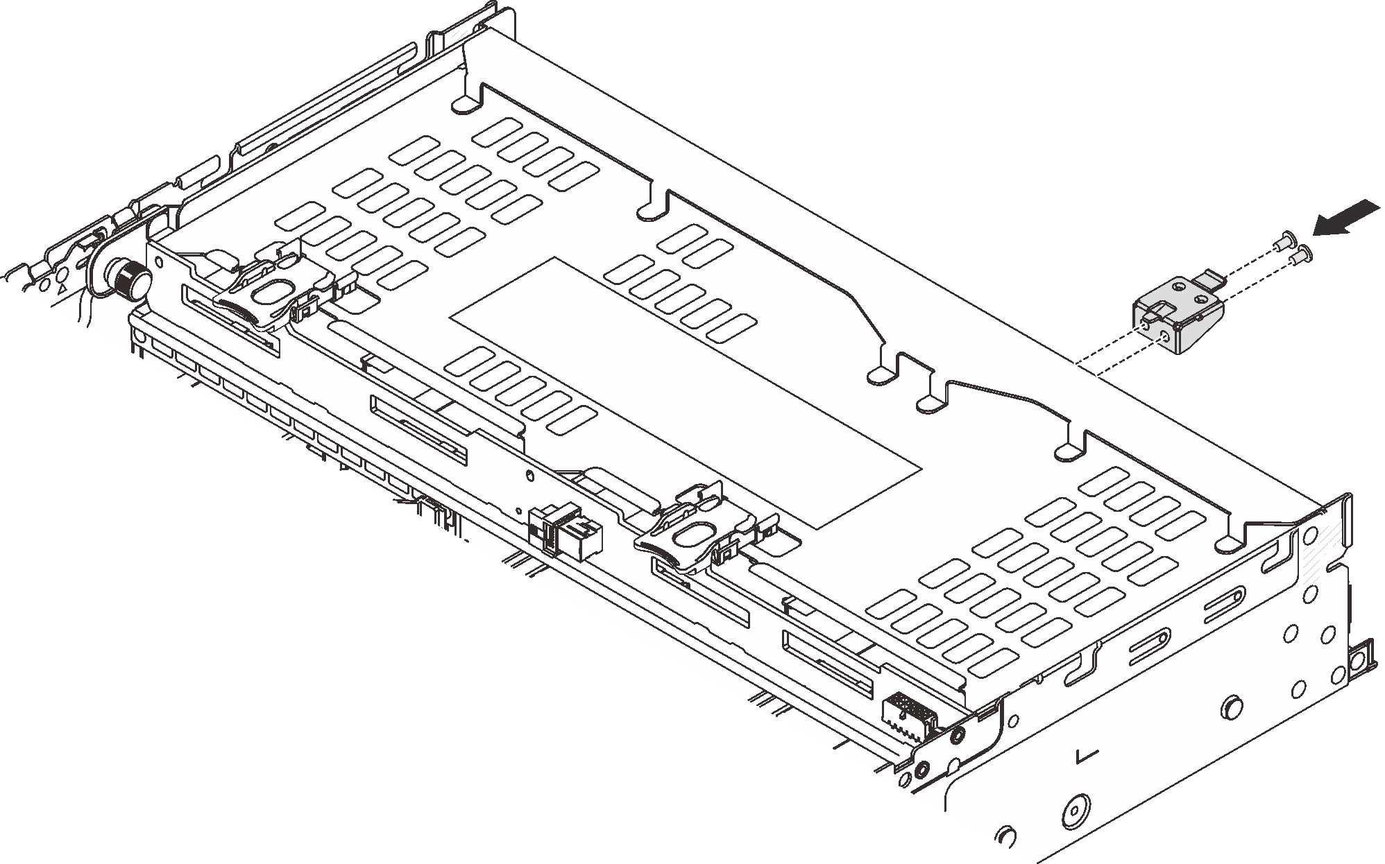
- Install the top cover support bracket.Figure 3. Installing the top cover support bracket
After you finish
Reinstall the drives or drive fillers into the rear drive cage. See Install a hot-swap drive.
Complete the parts replacement. See Complete the parts replacement.
Demo video