8i/16i RAID/HBA アダプター
以下は、1 つの 8i/16i RAID/HBA アダプターが搭載された 8 x 2.5 インチ AnyBay (Gen 5) 構成のケーブル接続を示しています。
コネクター間の接続: 1 ↔ 1、2 ↔ 2、3 ↔ 3、... n ↔ n
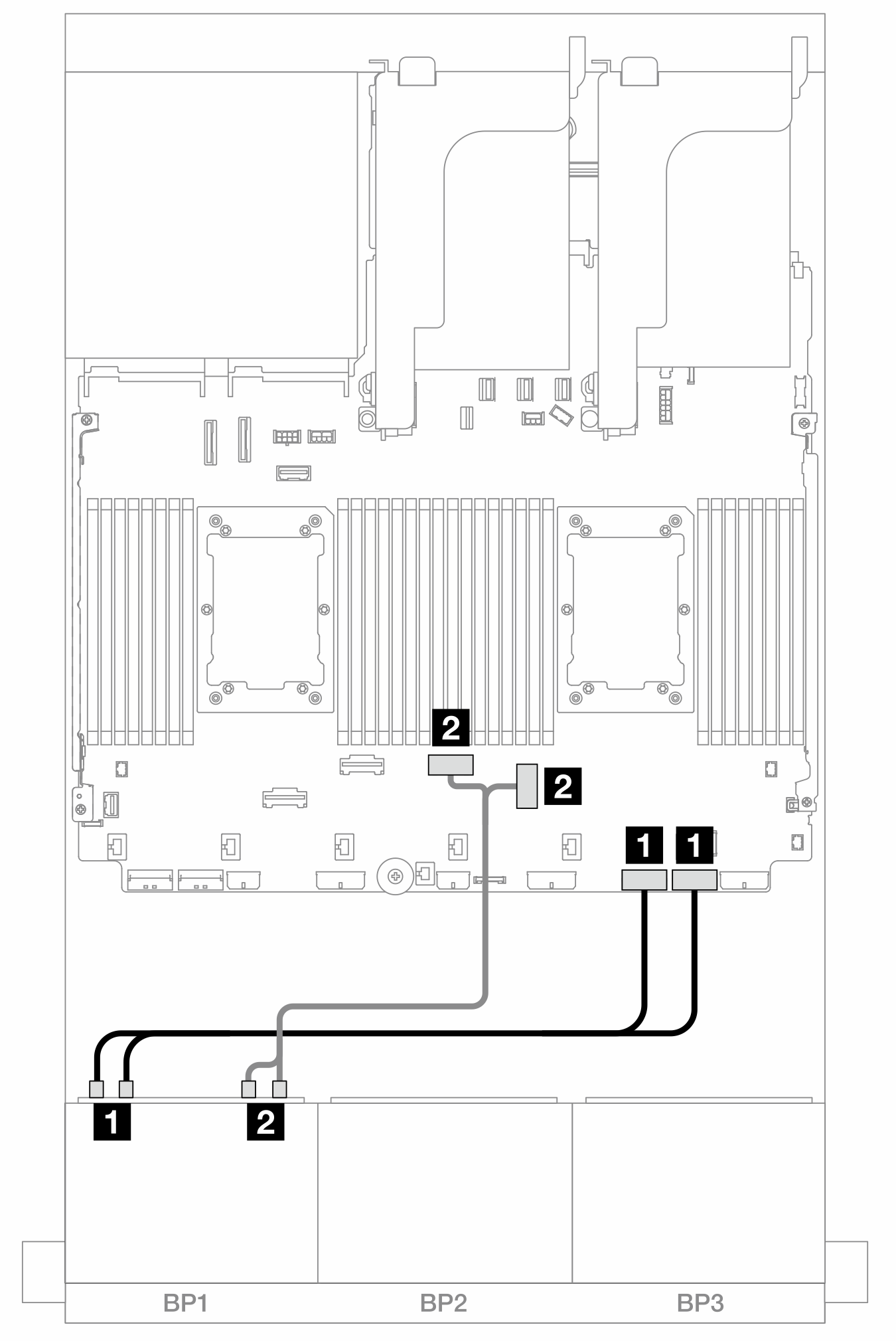
SAS/SATA ケーブル配線
図 1. 8i/16i RAID/HBA アダプターへの SAS/SATA ケーブル配線
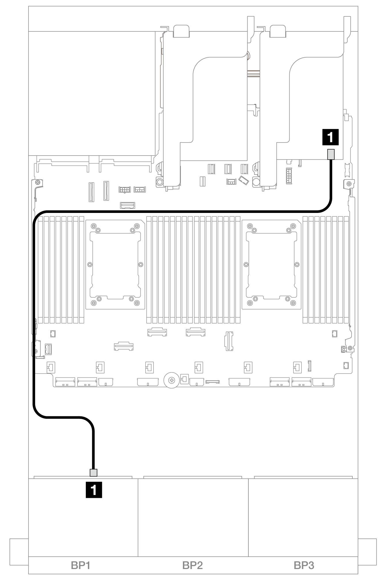
| 始点 | 終点 |
|---|---|
| 1 バックプレーン 1: SAS | 8i/16i アダプター
|
NVMe ケーブル配線
2 つのプロセッサーが取り付けられた場合のケーブル配線
図 2. ライザー 3 なし、または x8/x8 ライザー・カードを搭載した 2 つの Platinum シリーズ・プロセッサーが取り付けられている場合のケーブル配線
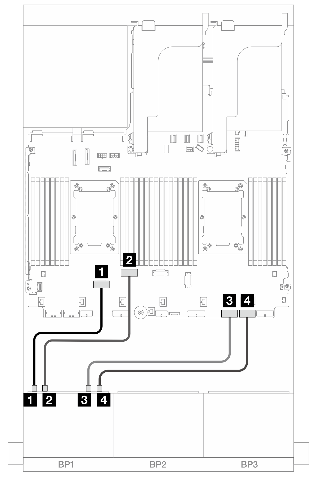
| 始点 | 終点 |
|---|---|
| 1 バックプレーン 1: NVMe 0-1 | オンボード: PCIe 6 |
| 2 バックプレーン 1: NVMe 2-3 | オンボード: PCIe 5 |
| 3 バックプレーン 1: NVMe 4-5 | オンボード: PCIe 2 |
| 4 バックプレーン 1: NVMe 6-7 | オンボード: PCIe 1 |
図 3. x16/x16 ライザー・カードを搭載した 2 つの Platinum シリーズ・プロセッサーが取り付けられている場合のケーブル配線
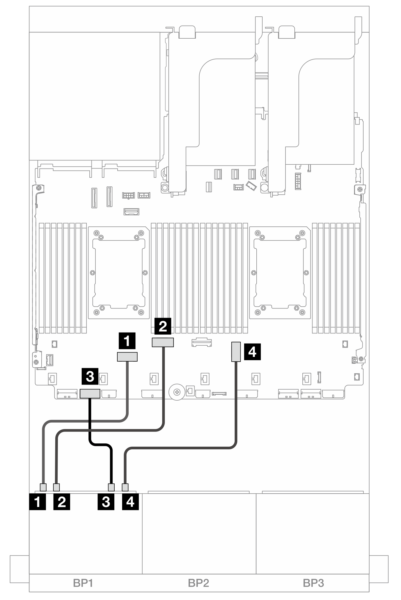
| 始点 | 終点 |
|---|---|
| 1 バックプレーン 1: NVMe 0-1 | オンボード: PCIe 6 |
| 2 バックプレーン 1: NVMe 2-3 | オンボード: PCIe 5 |
| 3 バックプレーン 1: NVMe 4-5 | オンボード: PCIe 7 |
| 4 バックプレーン 1: NVMe 6-7 | オンボード: PCIe 3 |
図 4. その他のシナリオでのケーブル配線
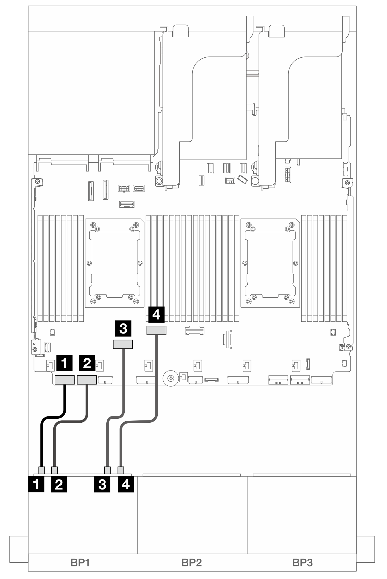
| 始点 | 終点 |
|---|---|
| 1 バックプレーン 1: NVMe 0-1 | オンボード: PCIe 8 |
| 2 バックプレーン 1: NVMe 2-3 | オンボード: PCIe 7 |
| 3 バックプレーン 1: NVMe 4-5 | オンボード: PCIe 6 |
| 4 バックプレーン 1: NVMe 6-7 | オンボード: PCIe 5 |
1 つのプロセッサーが取り付けられた場合のケーブル配線
図 5. 1 つのプロセッサーが取り付けられた場合のケーブル配線
| 始点 | 終点 |
|---|---|
| 1 バックプレーン 1: NVMe 0-1、2-3 | オンボード: PCIe 2、1 |
| 2 バックプレーン 1: NVMe 4-5, 6-7 | オンボード: PCIe 3、4 |
フィードバックを送る