Front view
The front view of the server varies by model. Depending on the model, your server might look slightly different from the illustrations in this topic.
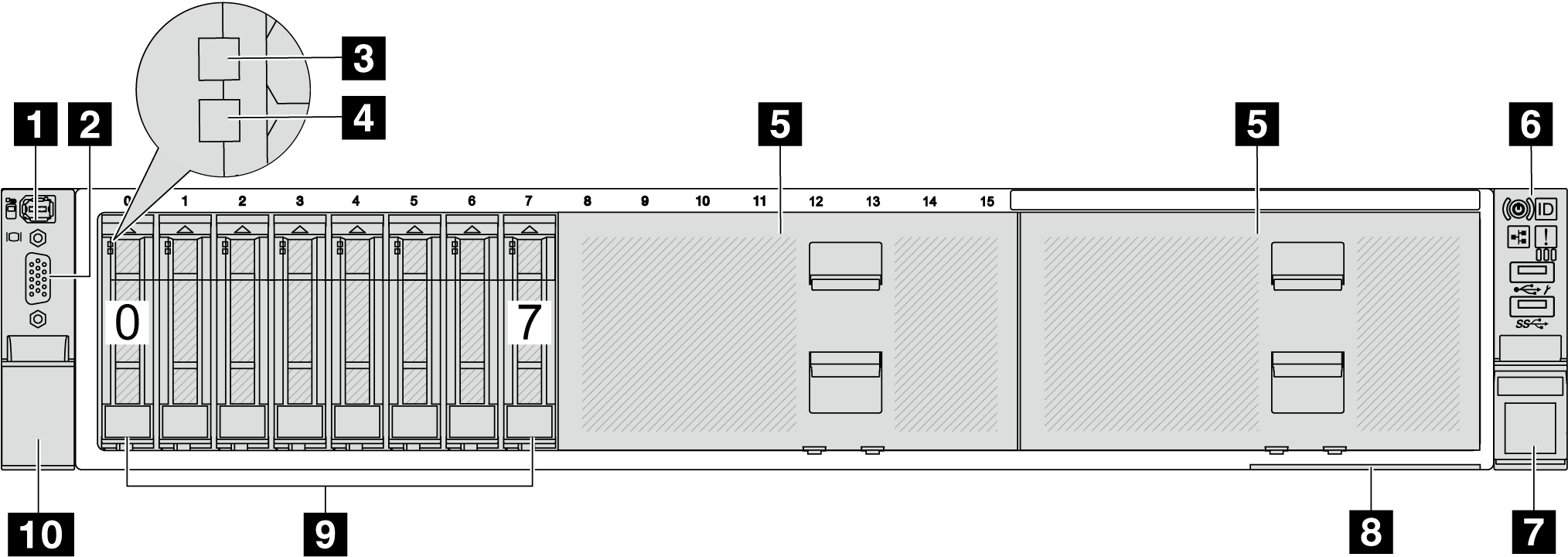
Front view with eight 2.5-inch front drive bays (model 1)
| Callout | Callout |
|---|---|
| 1 External diagnostics connector (optional) | 2 VGA connector (optional) |
| 3 Drive activity LED | 4 Drive status LED |
| 5 Drive bay fillers | 6 Front I/O module (on rack latch) |
| 7 Rack latch (right) | 8 Pull-out information tab |
| 9 Drive bays | 10 Rack latch (left) |
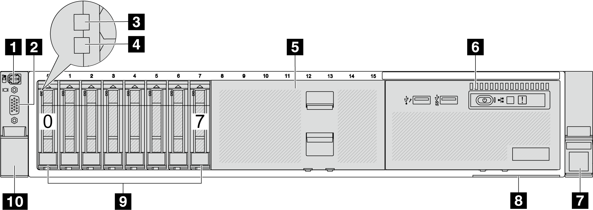
Front view with eight 2.5-inch front drive bays (model 2)
| Callout | Callout |
|---|---|
| 1 External diagnostics connector (optional) | 2 VGA connector (optional) |
| 3 Drive activity LED | 4 Drive status LED |
| 5 Drive bay filler | 6 Front I/O module (on media bay) |
| 7 Rack latch (right) | 8 Pull-out information tab |
| 9 Drive bays | 10 Rack latch (left) |
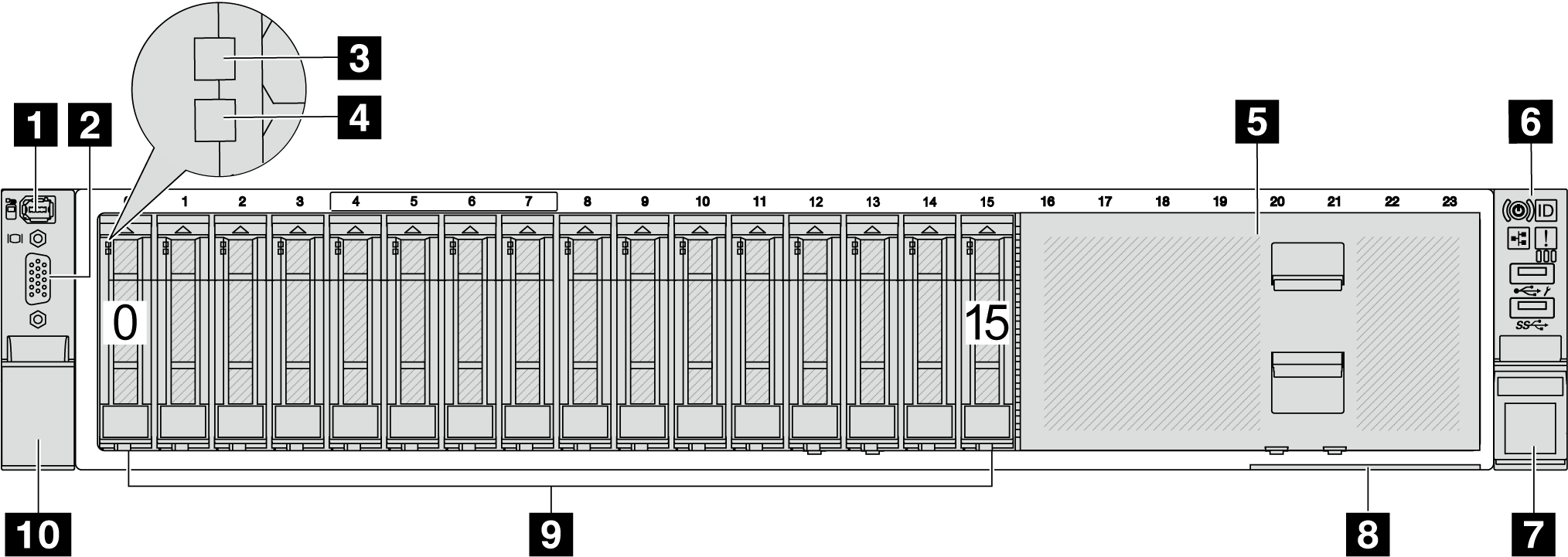
Front view with sixteen 2.5-inch front drive bays (model 1)
| Callout | Callout |
|---|---|
| 1 External diagnostics connector (optional) | 2 VGA connector (optional) |
| 3 Drive activity LED | 4 Drive status LED |
| 5 Drive bay filler | 6 Front I/O module (on rack latch) |
| 7 Rack latch (right) | 8 Pull-out information tab |
| 9 Drive bays | 10 Rack latch (left) |
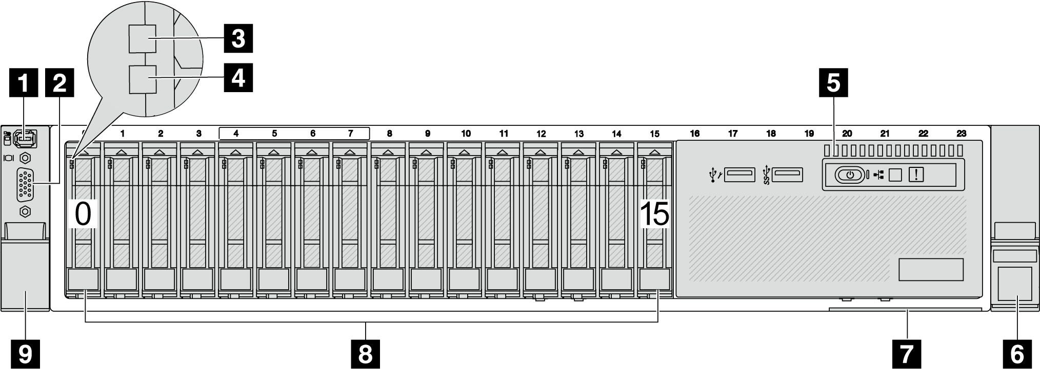
Front view with sixteen 2.5-inch front drive bays (model 2)
| Callout | Callout |
|---|---|
| 1 External diagnostics connector (optional) | 2 VGA connector (optional) |
| 3 Drive activity LED | 4 Drive status LED |
| 5 Front I/O module (on media bay) | 6 Rack latch (right) |
| 7 Pull-out information tab | 8 Drive bays |
| 9 Rack latch (left) |
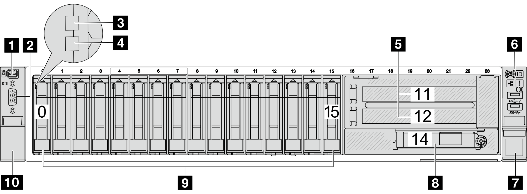
Front view with sixteen 2.5-inch front drive bays (model 3)
| Callout | Callout |
|---|---|
| 1 External diagnostics connector (optional) | 2 VGA connector (optional) |
| 3 Drive activity LED | 4 Drive status LED |
| 5 PCIe slots (x2) | 6 Front I/O module (on rack latch) |
| 7 Rack latch (right) | 8 Ethernet connectors on OCP module (optional) |
| 9 Drive bays | 10 Rack latch (left) |
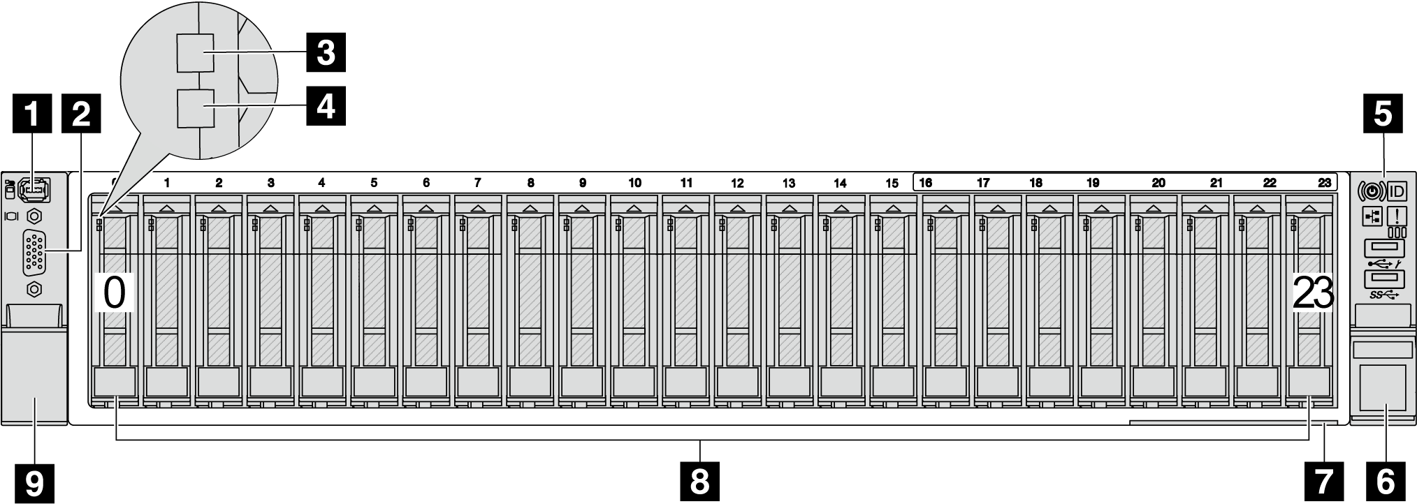
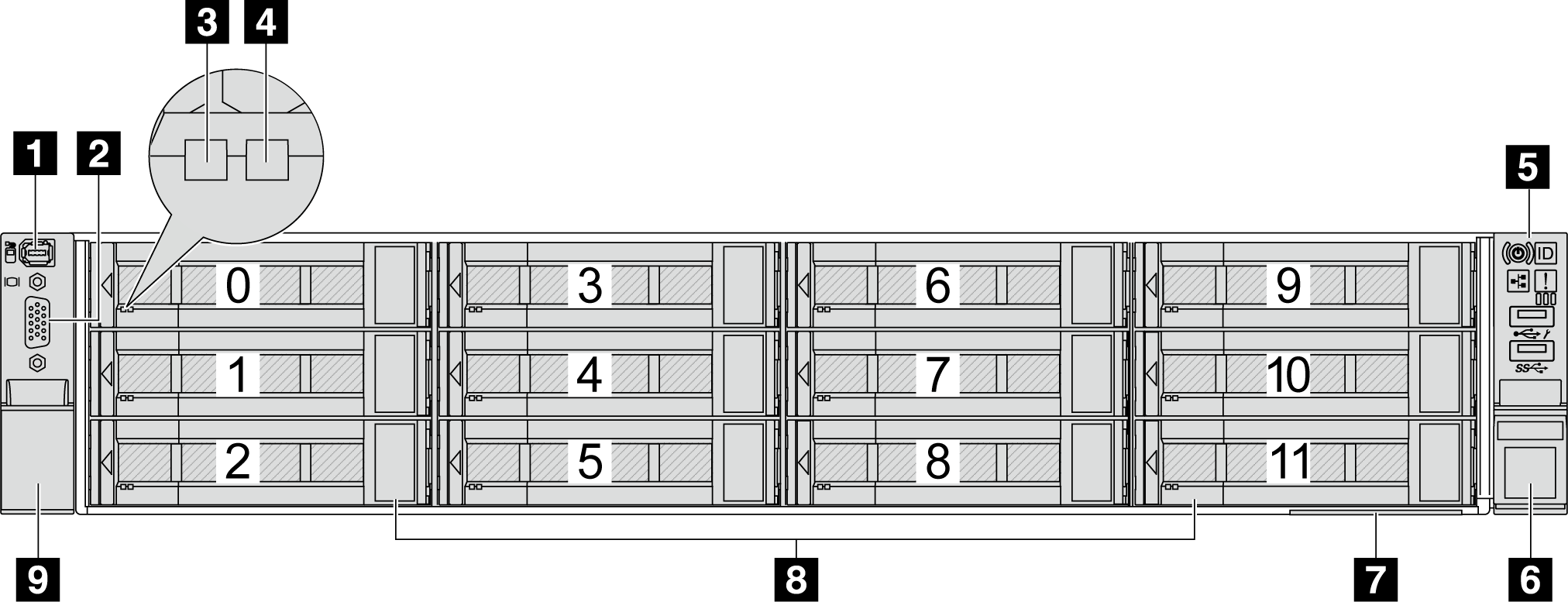
Front view with twenty-four 2.5-inch front drive bays
| Callout | Callout |
|---|---|
| 1 External diagnostics connector (optional) | 2 VGA connector (optional) |
| 3 Drive activity LED | 4 Drive status LED |
| 5 Front I/O module (on rack latch) | 6 Rack latch (right) |
| 7 Pull-out information tab | 8 Drive bays |
| 9 Rack latch (left) |
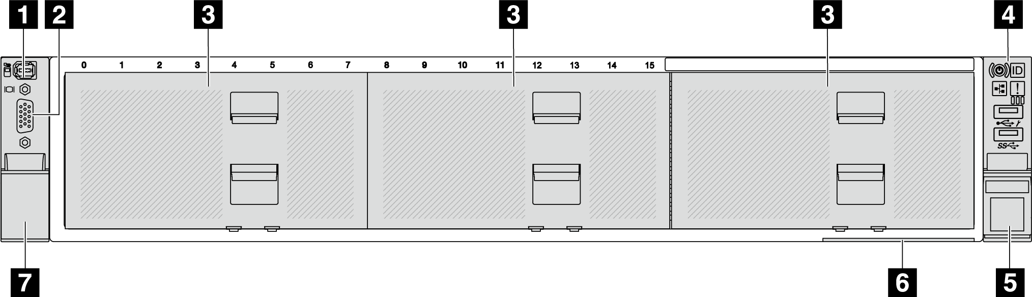
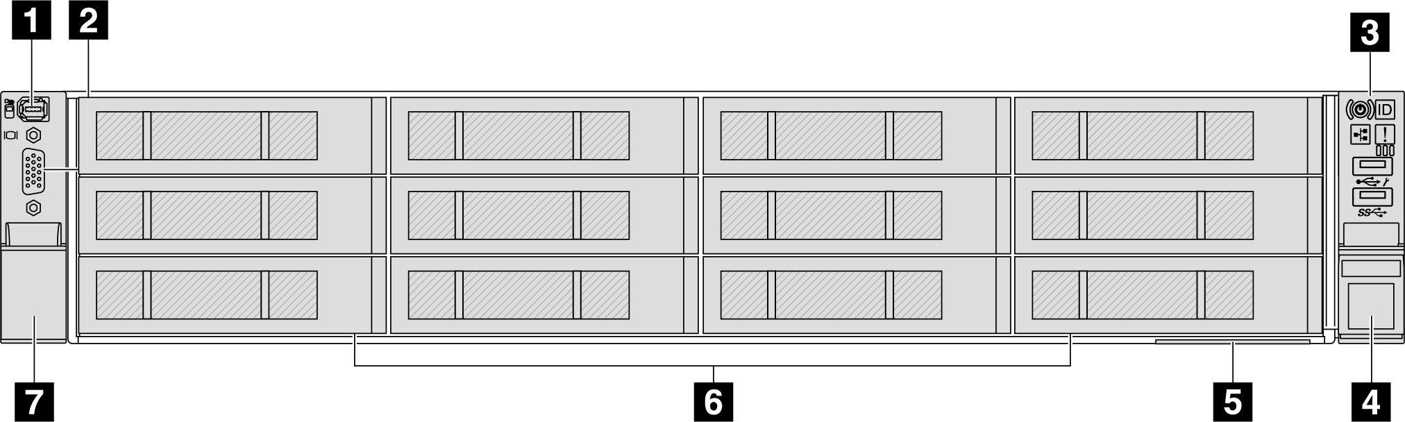
Front view with 2.5-inch front drive bays (backplane-less)
| Callout | Callout |
|---|---|
| 1 External diagnostics connector (optional) | 2 VGA connector (optional) |
| 3 Drive bay fillers | 4 Front I/O module (on rack latch) |
| 5 Rack latch (right) | 6 Pull-out information tab |
| 7 Rack latch (left) |
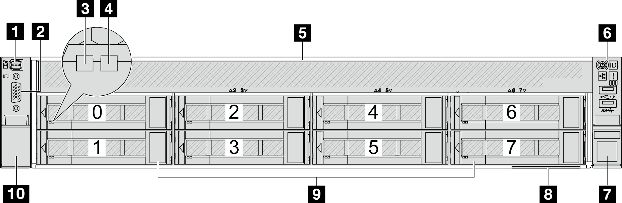
Front view with eight 3.5-inch front drive bays
| Callout | Callout |
|---|---|
| 1 External diagnostics connector (optional) | 2 VGA connector (optional) |
| 3 Drive activity LED | 4 Drive status LED |
| 5 Drive bay filler | 6 Front I/O module (on rack latch) |
| 7 Rack latch (right) | 8 Pull-out information tab |
| 9 Drive bays | 10 Rack latch (left) |
Front view with twelve 3.5-inch front drive bays
| Callout | Callout |
|---|---|
| 1 External diagnostics connector (optional) | 2 VGA connector (optional) |
| 3 Drive activity LED | 4 Drive status LED |
| 5 Front I/O module (on rack latch) | 6 Rack latch (right) |
| 7 Pull-out information tab | 8 Drive bays |
| 9 Rack latch (left) |
Front view with 3.5-inch front drive bays (backplane-less)
| Callout | Callout |
|---|---|
| 1 External diagnostics connector (optional) | 2 VGA connector (optional) |
| 3 Front I/O module (on rack latch) | 4 Rack latch (right) |
| 5 Pull-out information tab | 6 Drive bay fillers |
| 7 Rack latch (left) |
Front components overview
Drive bays
The drive bays on the front and rear of your server are designed for hot-swap drives. The number of the installed drives in your server varies by model. When you install drives, follow the order of the drive bay numbers.
Drive bay filler
The drive bay filler is used to cover a vacant drive bay. The EMI integrity and cooling of the server are protected by having all drive bays occupied. The vacant drive bays must be occupied by drive bay fillers or drive fillers.
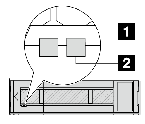
Drive LEDs
Each hot-swap drive comes with an activity LED and status LED and the signals are controlled by the backplanes. Different colors and speeds indicate different activities or status of the drive. The following illustration shows the LEDs on a hard disk drive or solid-state drive.
| Drive LED | Status | Description |
|---|---|---|
| 1 Drive activity LED (left) | Solid green | The drive is powered but not active. |
| Blinking green | The drive is active. | |
| 2 Drive status LED (right) | Solid yellow | The drive has an error. |
| Blinking yellow (blinking slowly, about one flash per second) | The drive is being rebuilt. | |
| Blinking yellow (blinking rapidly, about four flashes per second) | The drive is being identified. |
External diagnostics connector
The connector is for connecting an external diagnostics handset. For more about its functions, see External diagnostics handset
Front I/O module
The front IO module provides controls, connectors, and LEDs. The front I/O module varies by model. For more information, see Front I/O module.
PCIe slots
The PCIe slots are on the rear or front of the server, and your server supports up to 12 PCIe slots. For more information, see PCIe slots and PCIe adapters.
Pull-out information tab
The Lenovo XClarity Controller network access label is attached on the pull-out information tab. The default Lenovo XClarity Controller hostname and the IPv6 Link Local Address (LLA) are provided on the tab.
For more information, see Set the network connection for the Lenovo XClarity Controller.
Rack latch
If your server is installed in a rack, you can use the rack latches to help you slide the server out of the rack. You also can use the rack latches and screws to secure the server in the rack so that the server cannot slide out, especially in vibration-prone areas.
VGA connector
The VGA connectors on the front and rear of the server can be used to attach a high-performance monitor, a direct-drive monitor, or other devices that use a VGA connector.
Ethernet connectors
Figure 2. OCP module (two connectors) 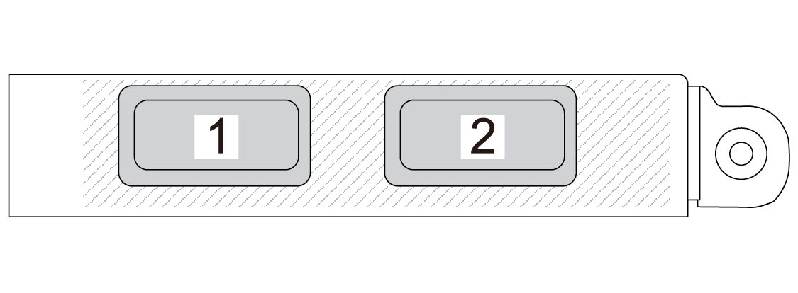 | Figure 3. OCP module (four connectors) 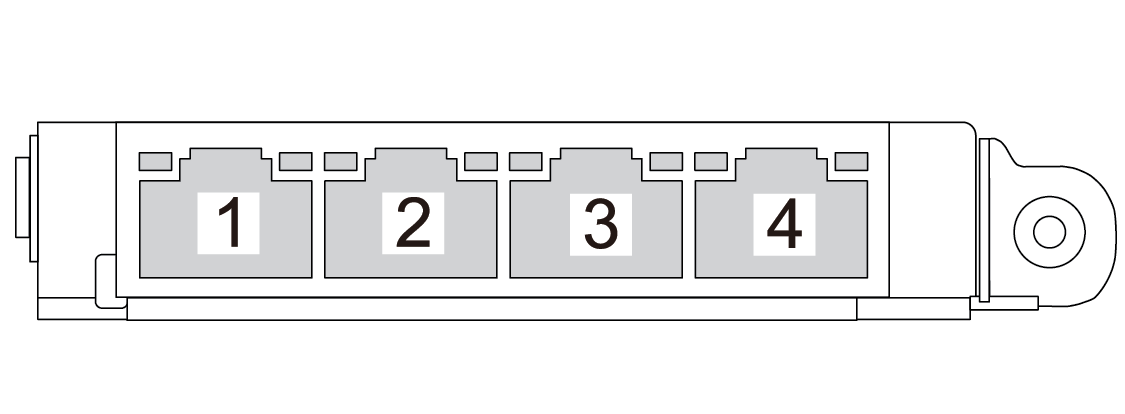 |
The OCP module provides two or four extra Ethernet connectors for network connections.
By default, one of the Ethernet connectors on the OCP module can also function as a management connector using the shared management capacity.