System-board-assembly connectors
The following illustration shows the internal connectors on the system board assembly which contains the system I/O board and processor board.
Figure 1. System-board-assembly connectors
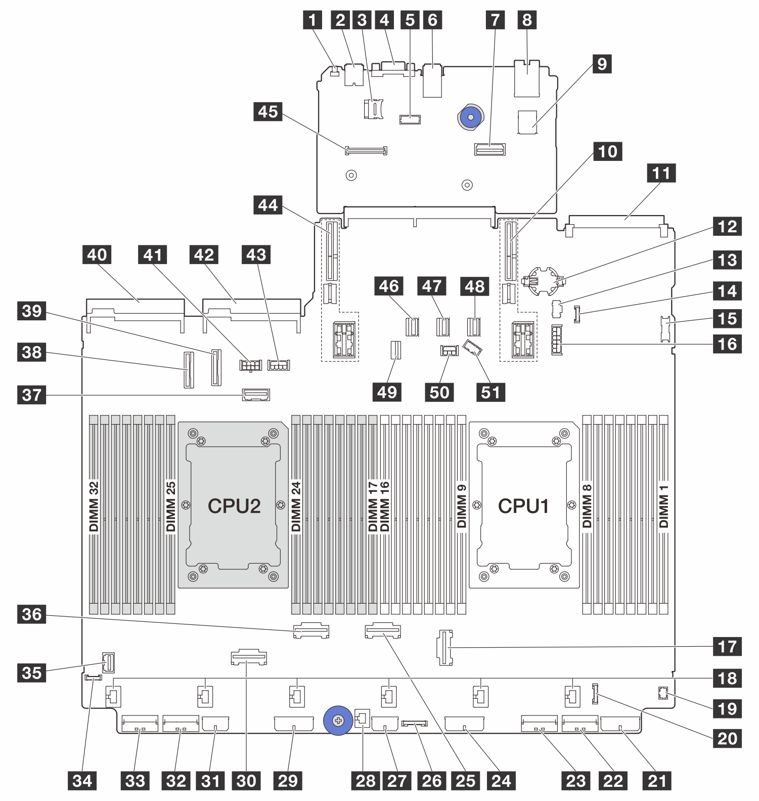
| 1 NMI button | 2 Rear USB connector |
| 3 MicroSD socket | 4 VGA connector |
| 5 Serial port connector | 6 Rear USB connectors |
| 7 Second management Ethernet connector | 8 XCC system management port |
| 9 Internal USB connector | 10 Riser 1 slot |
| 11 OCP 3.0 slot | 12 CMOS battery (CR2032) |
| 13 M.2 power connector | 14 Leak detection connector |
| 15 Front USB connector | 16 7mm backplane power connector |
| 17 PCIe connector 3 | 18 Fan connectors |
| 19 Front I/O connector (for Y cable) | 20 Front I/O connector |
| 21 Backplane 3 power connector | 22 PCIe connector 1 |
| 23 PCIe connector 2 | 24 Backplane 2 power connector |
| 25 PCIe connector 4 | 26 CFF Retimer connector |
| 27 CFF expander power connector | 28 Intrusion switch connector |
| 29 Backplane 1 power connector | 30 PCIe connector 6 |
| 31 CFF RAID/HBA power connector | 32 PCIe connector 7 |
| 33 PCIe connector 8 | 34 External diagnostics connector |
| 35 Front VGA connector | 36 PCIe connector 5 |
| 37 Riser 3 sideband connector | 38 PCIe connector 9 |
| 39 PCIe connector 10 | 40 Power supply 1 connector |
| 41 Riser 3 power connector | 42 Power supply 2 connector |
| 43 GPU power connector | 44 Riser 2 slot |
| 45 Firmware and RoT security module connector | 46 SATA connector 0 |
| 47 SATA connector 1 | 48 SATA connector 2 |
| 49 M.2/7mm backplane signal connector | 50 Backplane power connector |
| 51 Backplane sideband connector |
Note
The front I/O module on rack latch is connected to connector 20. See Front I/O connectors.
The front I/O module on media bay with an integrated diagnostics panel (an LCD diagnostics display) is connected to connector 20. See Front I/O connectors.
The front I/O module on media bay without LCD diagnostics display is connected to connectors 19 and 20 using a Y cable. See Front I/O connectors.
Give documentation feedback