Remove a processor and heat sink
This task has instructions for removing an assembled processor and heat sink, known as a processor-heat-sink module (PHM), a processor, and a heat sink. All of these tasks require a Torx T30 driver.
About this task
Read Installation Guidelines and Safety inspection checklist to ensure that you work safely.
Power off the server and peripheral devices and disconnect the power cords and all external cables. See Power off the server.
If the server is installed in a rack, slide the server out on its rack slide rails to gain access to the top cover, or remove the server from the rack. See Remove the server from rack.
Prevent exposure to static electricity, which might lead to system halt and loss of data, by keeping static-sensitive components in their static-protective packages until installation, and handling these devices with an electrostatic-discharge wrist strap or other grounding system.
Each processor socket must always contain a cover or a PHM. When removing or installing a PHM, protect empty processor sockets with a cover.
Do not touch the processor socket or processor contacts. Processor-socket contacts are very fragile and easily damaged. Contaminants on the processor contacts, such as oil from your skin, can cause connection failures.
Do not allow the thermal grease on the processor or heat sink to come in contact with anything. Contact with any surface can compromise the thermal grease, rendering it ineffective. Thermal grease can damage components, such as the electrical connectors in the processor socket.
Remove and install only one PHM at a time.
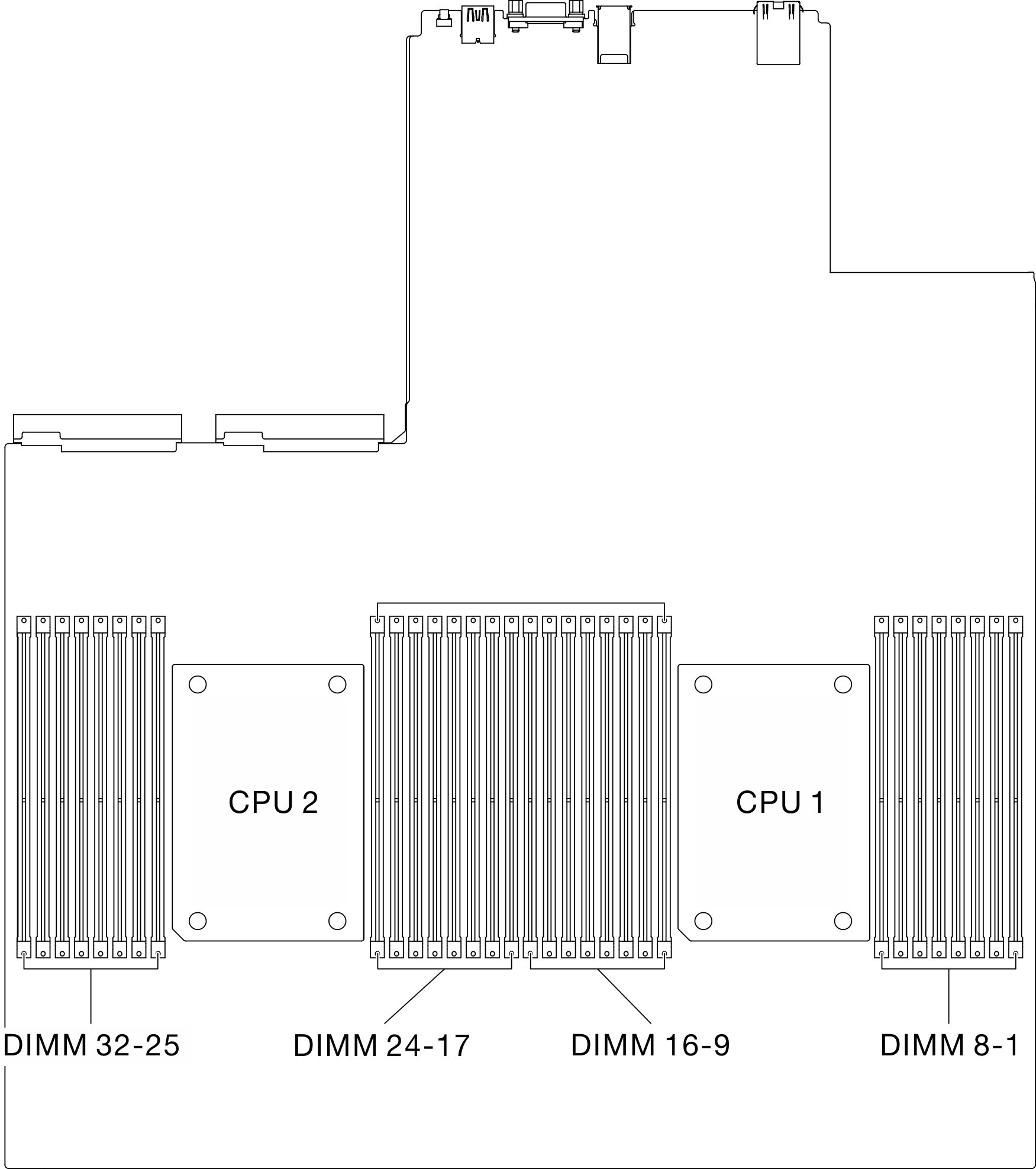
Install the PHM starting from processor socket 1.
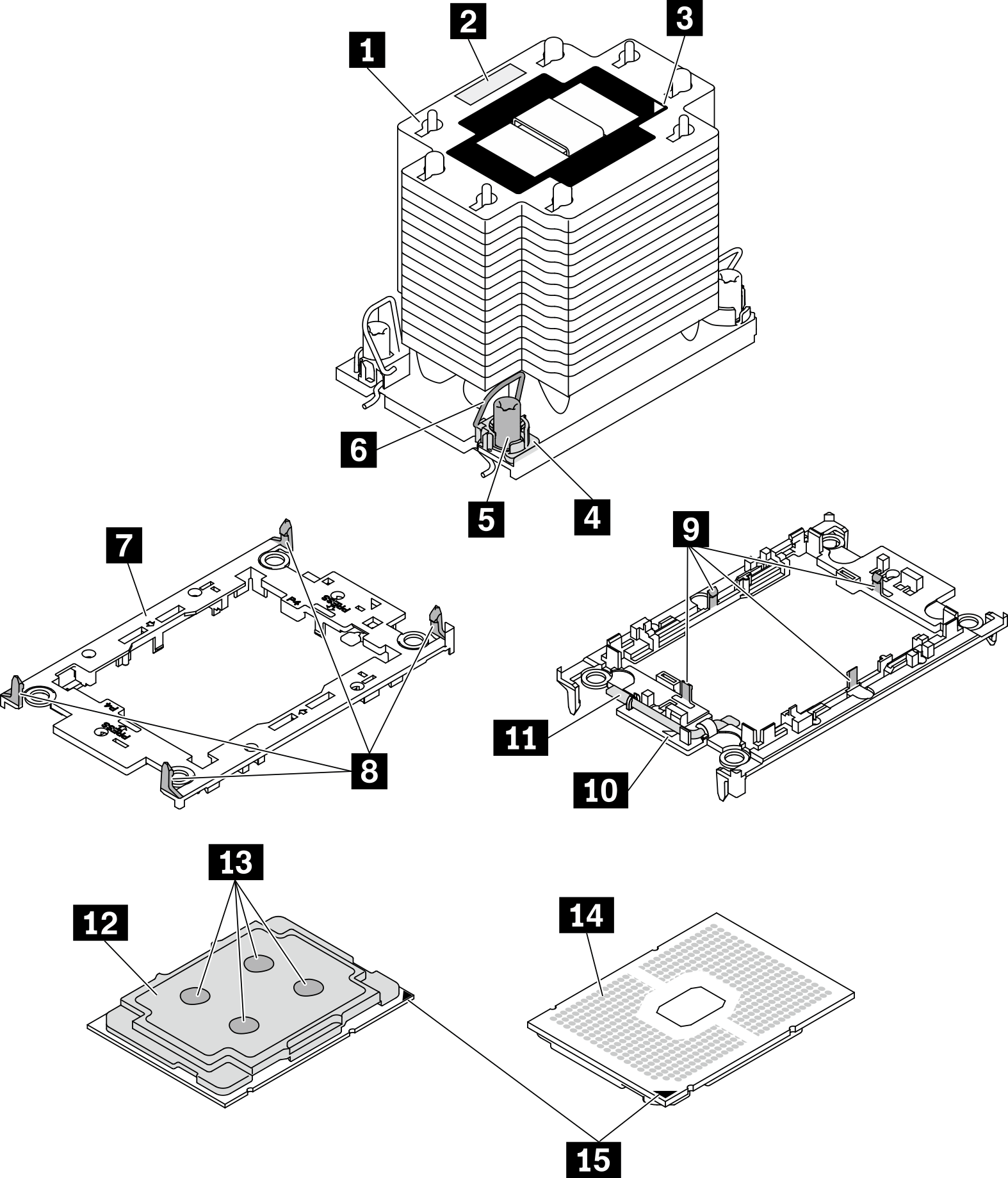
| 1 Heat sink | 9 Clips to secure processor in carrier |
| 2 Processor identification label | 10 Carrier triangular mark |
| 3 Heat sink triangular mark | 11 Processor ejector handle |
| 4 Nut and wire bail retainer | 12 Processor heat spreader |
| 5 Torx T30 nut | 13 Thermal grease |
| 6 Anti-tilt wire bail | 14 Processor contacts |
| 7 Processor carrier | 15 Processor triangular mark |
| 8 Clips to secure carrier to heat sink |
Procedure
- Prepare your sever.
- Remove the top cover. See Remove the top cover.
- Remove the air baffle. See Remove the air baffle.
- Remove the PHM from the system board.
 Fully loosen the Torx T30 nuts on the PHM in the removal sequence shown on the heat sink label.
 Rotate the anti-tilt wire bails on the heat sink inward.
 Carefully lift the PHM from the processor socket. If the PHM cannot be fully lifted out of the socket, further loosen the Torx T30 nuts and try lifting the PHM again.
- Place the PHM upside down with the processor-contact side up.Note
Do not touch the contacts on the processor.
Keep the processor socket clean from any object to prevent possible damages.
Figure 3. PHM removal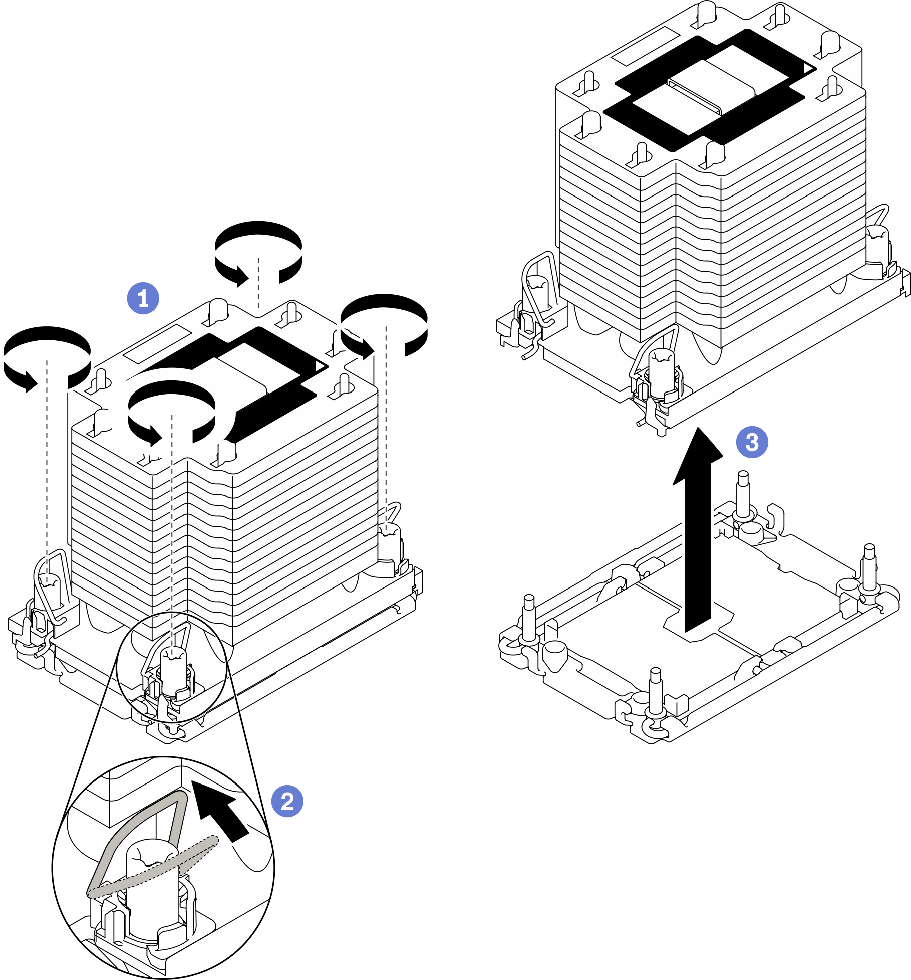
Empty processor socket must always contain a socket cover and a filler before the server is powered on.
If you are removing the PHM as part of a system board replacement, set the PHM aside.
If you are reusing the processor or heat sink, separate the processor from its carrier. See Separate the processor from carrier and heat sink
If you are instructed to return the defective component, package the part to prevent any shipping damage. Reuse the packaging the new part arrived in and follow all packaging instructions.
Demo video