SXM5 PCIe switch board cable routing
Use the section to understand the cable routing for the SXM5 PCIe switch board.
Note
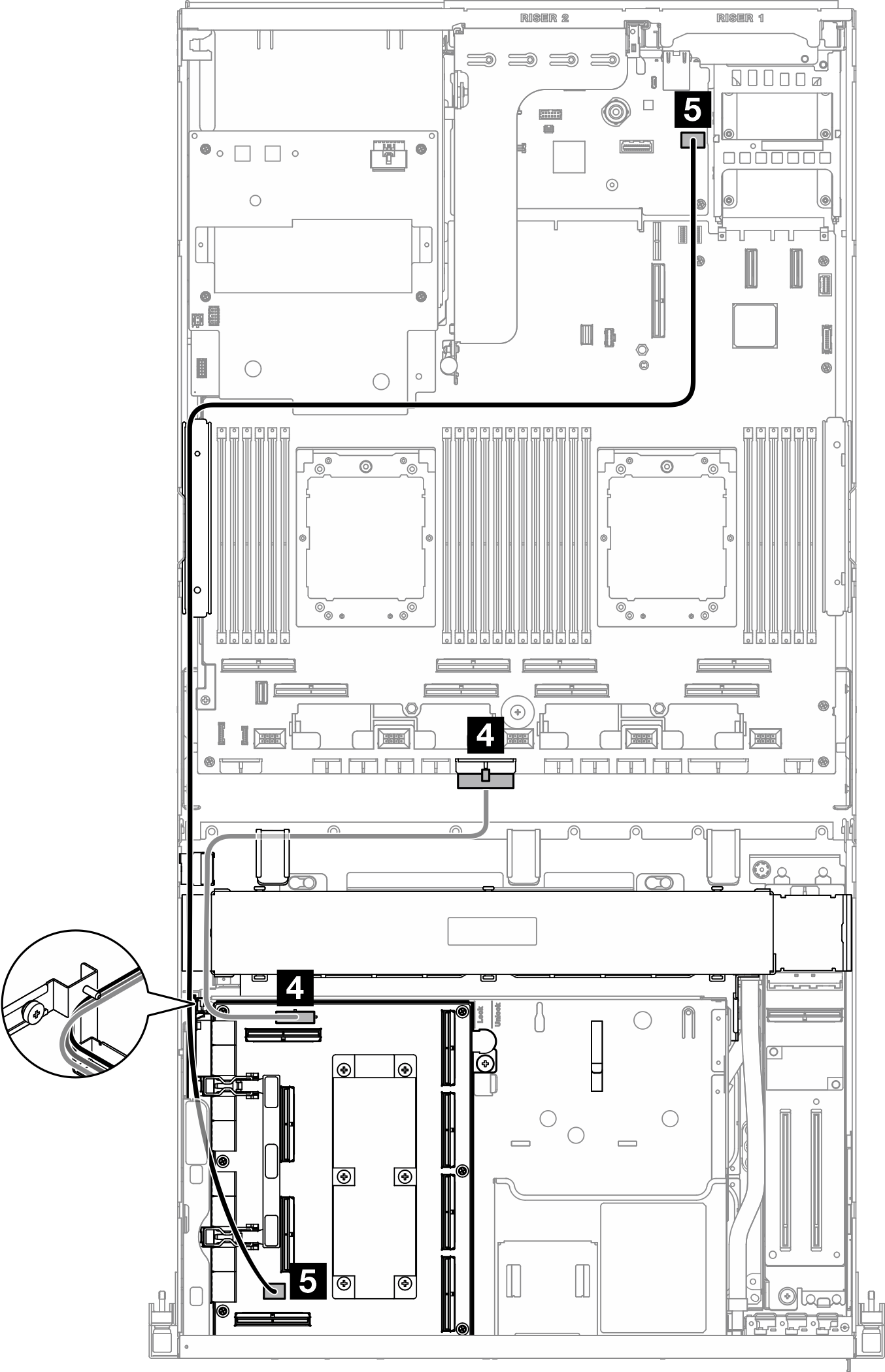
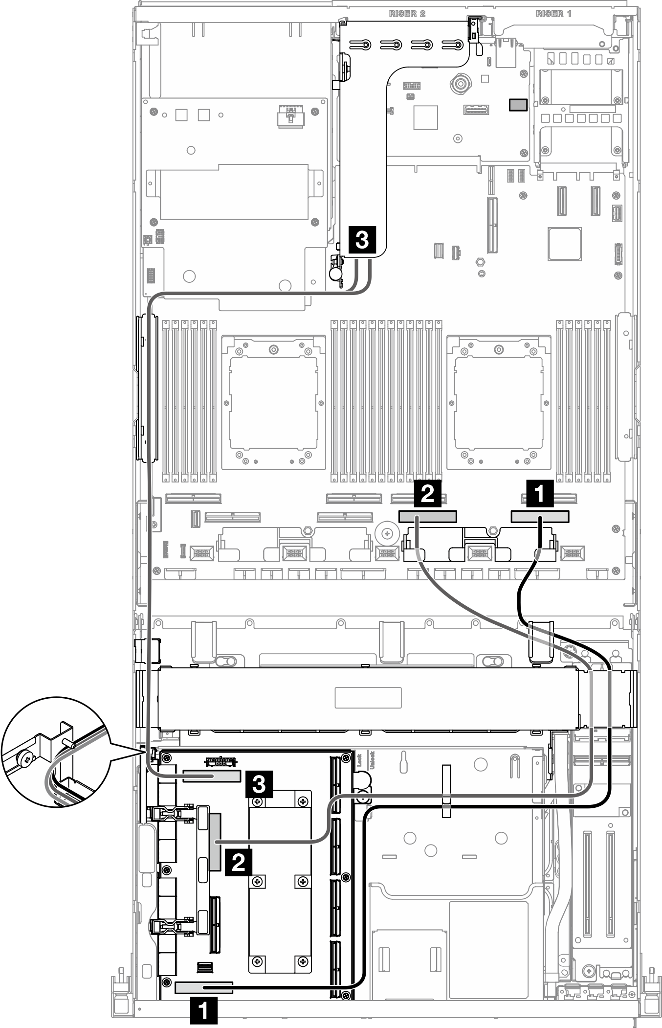
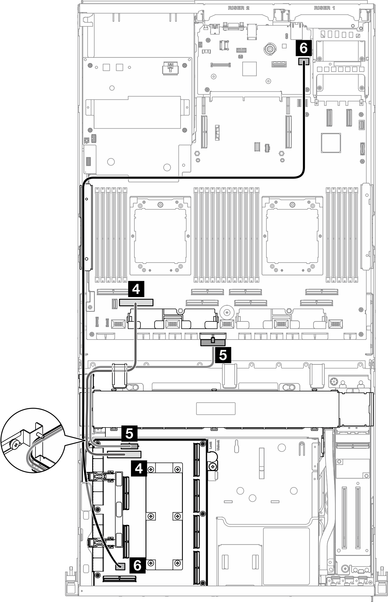
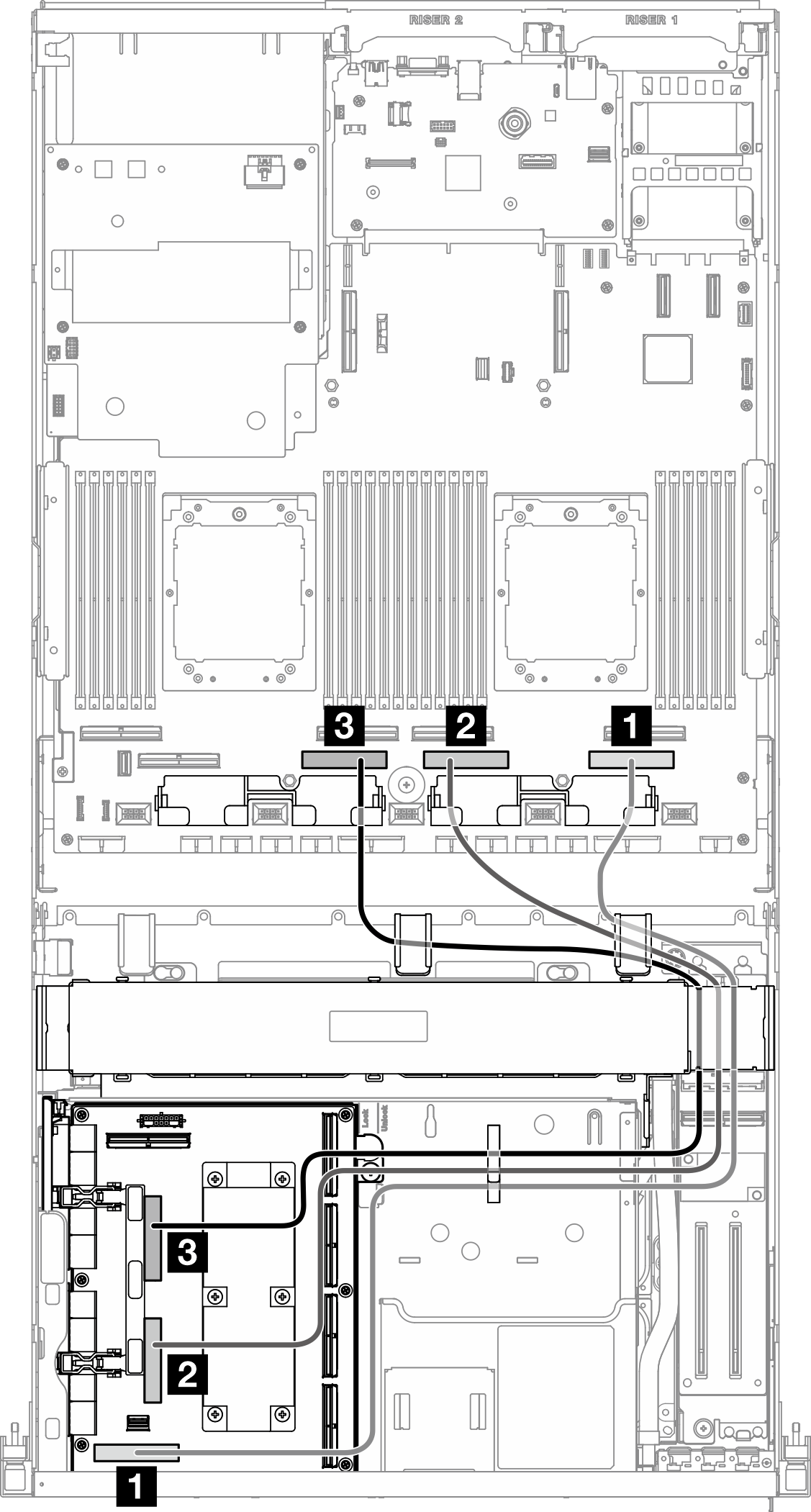
- Make sure the cables that go through the right side of the server are routed under the radiator bracket as illustrated.
- Make sure the cables that go through the left side of the server are routed above the radiator bracket as illustrated.
- Connect the power cable last; then, press the power cable down to secure all the cables under the cable retaining guide on the front drive tray as illustrated.
- After connecting cables, equally divide the cables that go through the right side of the front drive tray into two bundles, and secure them with the two cable ties.Figure 1. Securing cables with cable ties

Choose the routing plan according to the number of processor installed in the system:
One processor — configurations 7 and 25
 |  |
| Cable | From | To |
|---|---|---|
| 1 | SXM5 PCIe switch board: MCIO connector H | System board assembly: PCIe connector 1 |
| 2 | SXM5 PCIe switch board: MCIO connector F | System board assembly: PCIe connector 3 |
| 3 | SXM5 PCIe switch board: Power connector | System board assembly: PCIe distribution board power connector |
| 4 | SXM5 PCIe switch board: GPU management connector | System board assembly: Front SXM5 GPU management PCIe connector |
Two processors — configurations 8 and 26
 |  |
| Cable | From | To |
|---|---|---|
| 1 | SXM5 PCIe switch board: MCIO connector H | System board assembly: PCIe connector 1 |
| 2 | SXM5 PCIe switch board: MCIO connector G | System board assembly: PCIe connector 3 |
| 3 | SXM5 PCIe switch board: MCIO connector F | System board assembly: PCIe connector 5 |
| 4 | SXM5 PCIe switch board: MCIO connector E | System board assembly: PCIe connector 7 |
| 5 | SXM5 PCIe switch board: Power connector | System board assembly: PCIe distribution board power connector |
| 6 | SXM5 PCIe switch board: GPU management connector | System board assembly: Front SXM5 GPU management PCIe connector |
Give documentation feedback