Front I/O expansion board cable routing
Use the section to understand the cable routing for the front I/O expansion board.
This section applies to configurations 7, 8, 25, and 26.
Note
After connecting cables, equally divide the cables that go through the right side of the front drive tray into two bundles, and secure them with the two cable ties.
Figure 1. Securing cables with cable ties
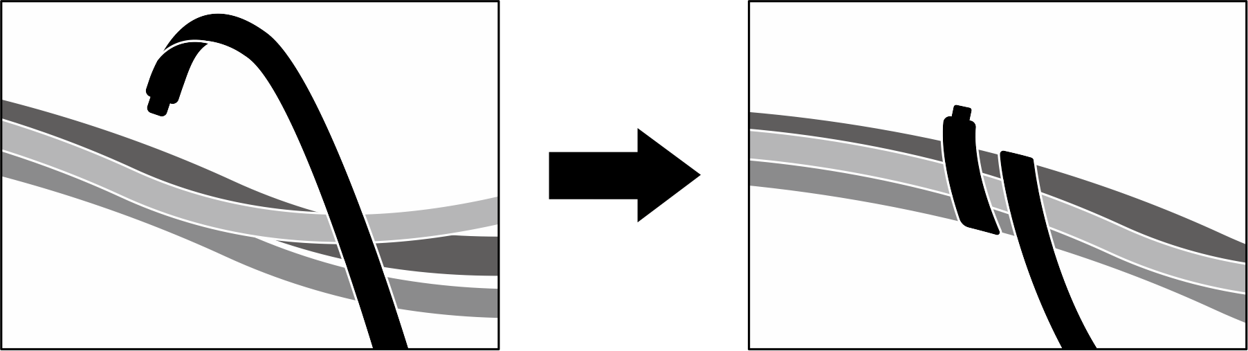
Figure 2. Front I/O expansion board cable routing
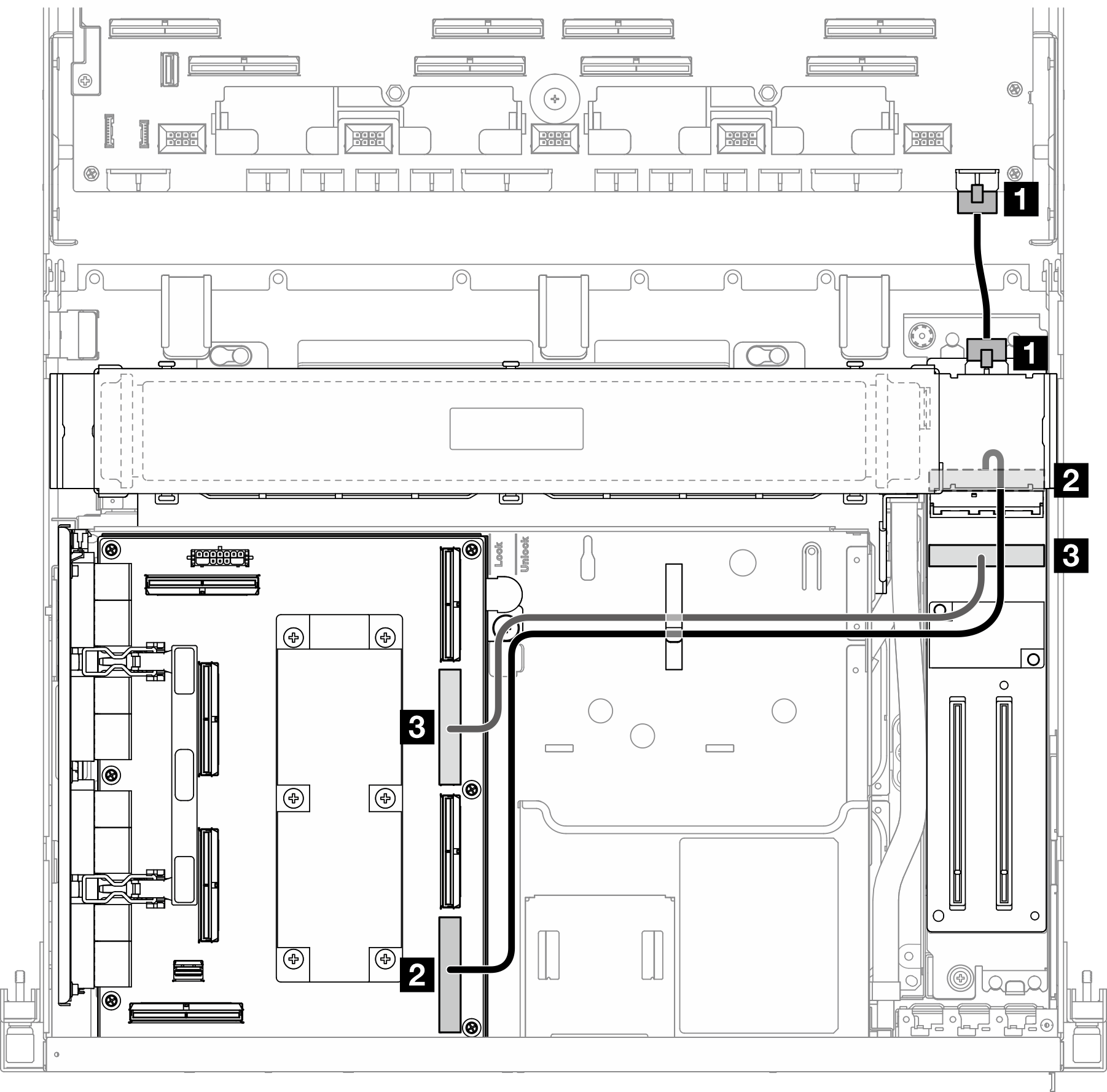
| Cable | From | To |
|---|---|---|
| 1 | Front I/O expansion board: Power connector | System board assembly: Front riser power connector |
| 2 | Front I/O expansion board: MCIO connector A | SXM5 PCIe switch board: MCIO connector D |
| 3 | Front I/O expansion board: MCIO connector B | SXM5 PCIe switch board: MCIO connector B |
Give documentation feedback