System-board-assembly LEDs
The following illustrations show the light-emitting diodes (LEDs) on the system board assembly.
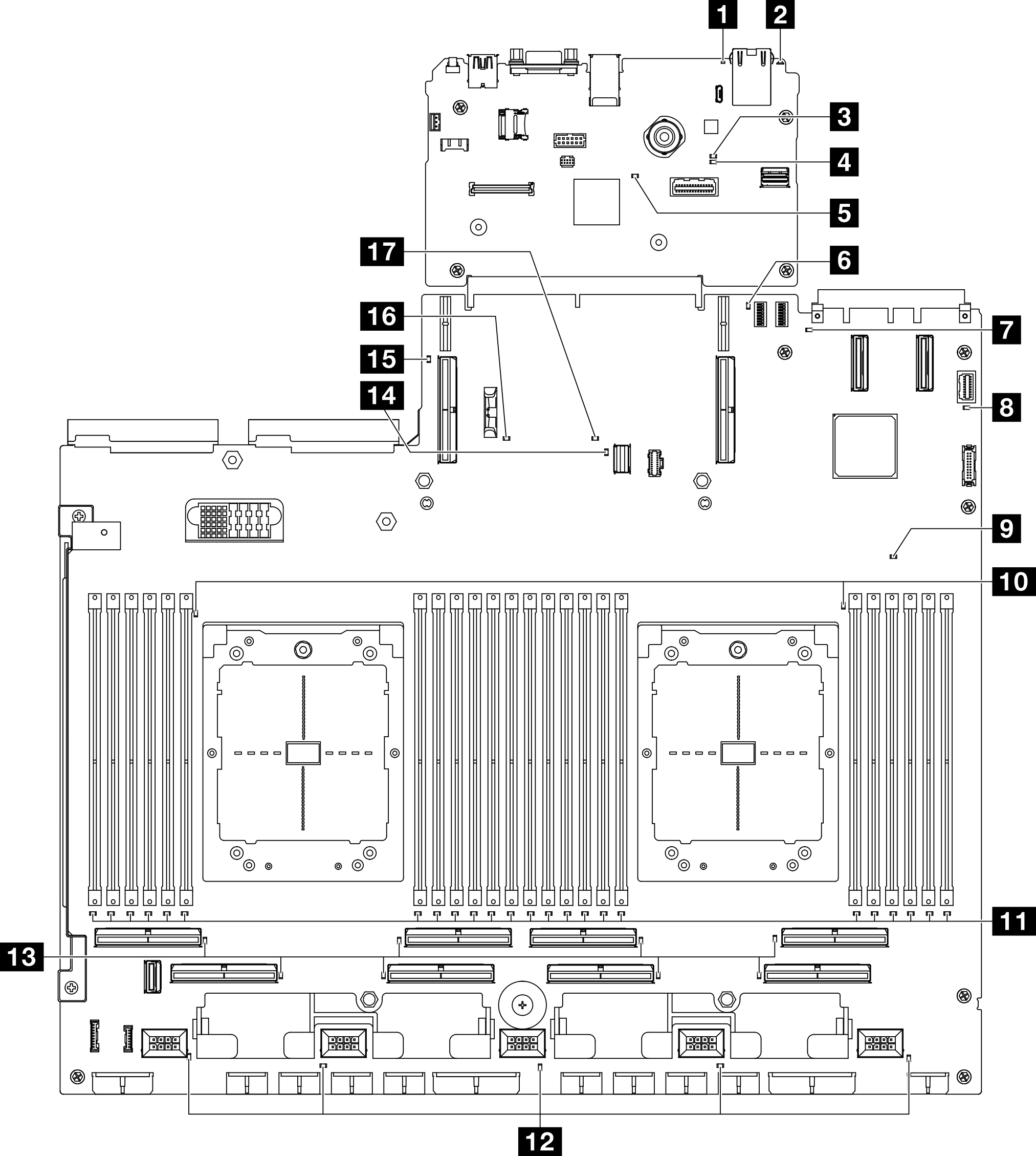
| LED | Description and actions |
|---|---|
| 1 System error LED (yellow) | LED on: an error has occurred. Complete the following steps:
|
| 2 Identification LED (blue) | This LED is used as a presence detection LED. You can use Lenovo XClarity Controller to light this LED remotely. Use this LED to locate the server among other servers visually. |
| 3 BMC status LED (green) | The states of the BMC status LED are as follows:
|
| 4 BMC heartbeat LED (green) | The BMC heartbeat LED helps you identify the BMC status.
|
| 5 SSP heartbeat LED (green) | The states of the SSP (Synchronous Serial Port) heartbeat LED are as follows:
|
| 6 Rear PCIe riser 1 error LED (yellow) | LED on: an error has occurred to the rear PCIe riser 1. |
| 7 OCP error LED (yellow) | LED on: an error has occurred to the OCP slot the LED represents. Complete the following steps:
|
| 8 System power LED (green) | The states of the power LED are as follows:
|
| 9 FPGA heartbeat LED (yellow) | This LED indicates power-on and power-off sequencing.
|
| 10 Processor error LEDs (yellow) | LED on: an error has occurred to the processor the LED represents. |
| 11 DIMM error LEDs (yellow) | LED on: an error has occurred to the DIMM the LED represents. |
| 12 Fan error LEDs (yellow) | LED on: an error has occurred to the fan the LED represents. |
| 13 PCIe connector error LEDs (yellow) | LED on: an error has occurred to the PCIe connector the LED represents. Complete the following steps:
|
| 14 M.2 error LED (yellow) | LED on: an error has occurred to the M.2. |
| 15 Rear PCIe riser 2 error LED (yellow) | LED on: an error has occurred to the rear PCIe riser 2. |
| 16 CMOS battery error LED (yellow) | The system CMOS battery is not installed or is not working. |
| 17 System board assembly error LED (yellow) | LED on: an error has occurred to the system board assembly. Complete the following steps:
|