Top view
The illustrations in this section provide information about the top view of the server.
Note
The illustrations in this section show the location of certain parts. Some parts may not be supported at the same time within certain configuration(s).
2U compute shuttle top view
Figure 1. 2U compute shuttle top view
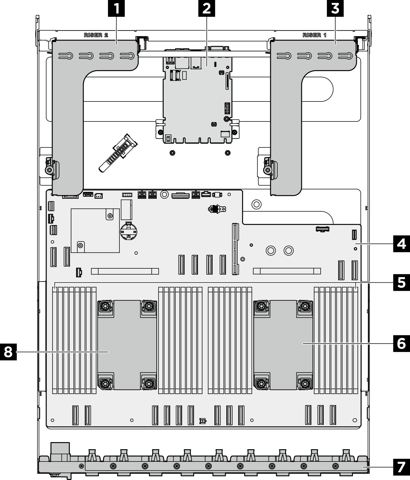
| 1 PCIe riser 2 | 2 System I/O board |
| 3 PCIe riser 1 | 4 System board |
| 5 Memory modules | 6 Processor 1 |
| 7 Rear PCIe switch cable harness | 8 Processor 0 |
8U GPU shuttle top view
Figure 2. 8U GPU shuttle top view
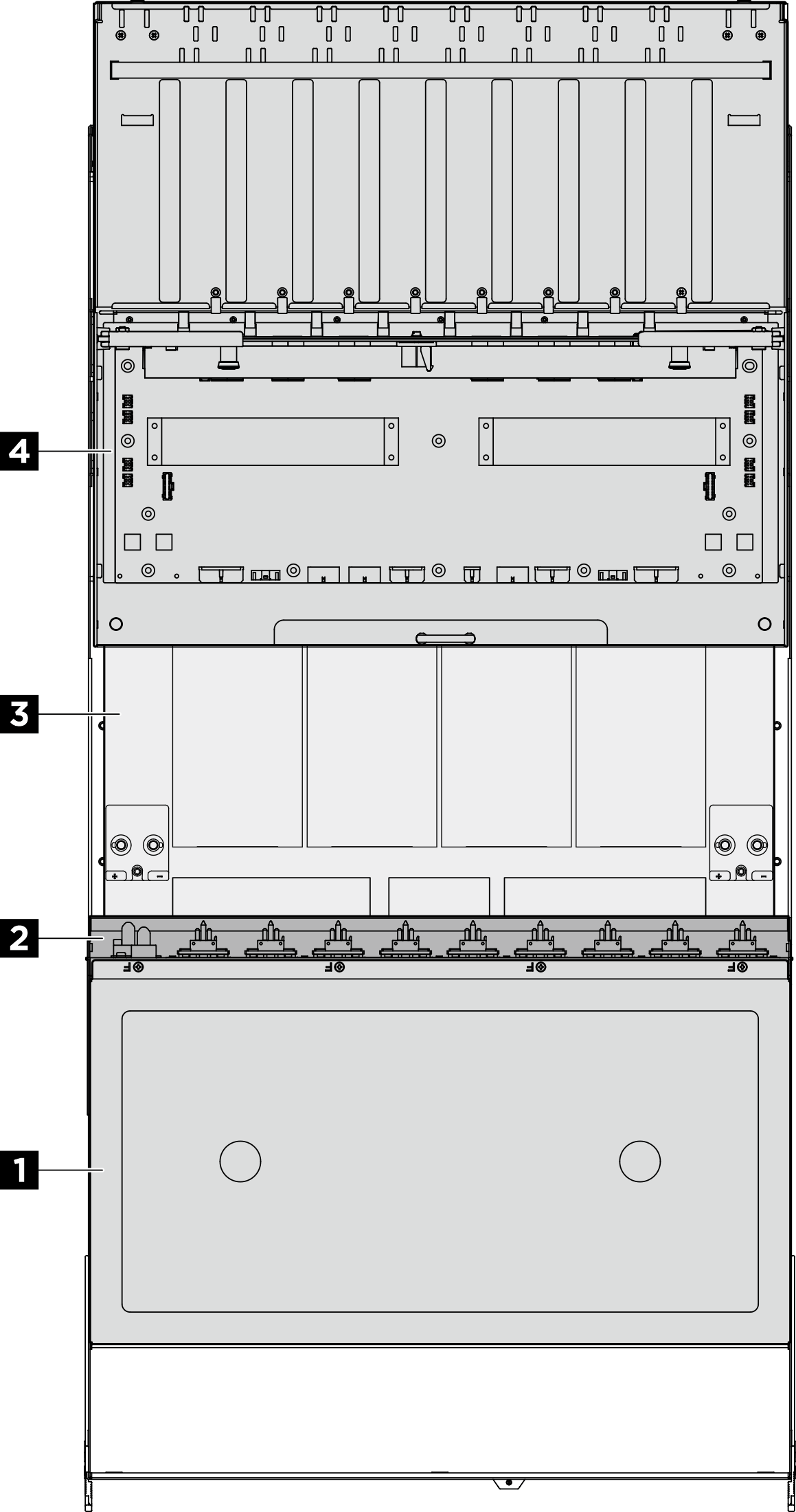
| 1 Cable cover | 2 Front PCIe switch cable harness |
| 3 GPU complex | 4 Power complex |
Give documentation feedback