System board switches
The following illustration shows the location of the switches, jumpers, and buttons on the system board.
Note
If there is a clear protective sticker on the top of the switch blocks, you must remove and discard it to access the switches.
Figure 1. System board switches
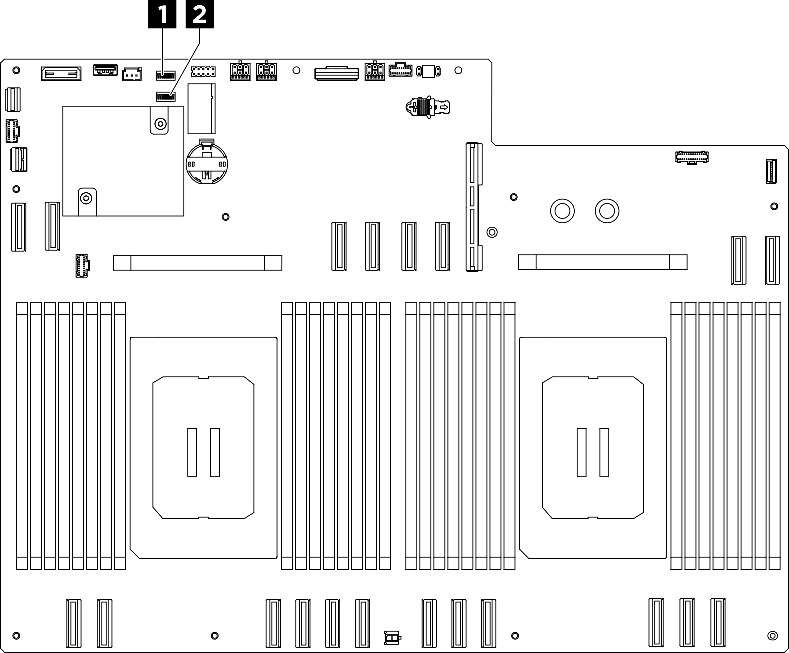
| 1 Switch block 5 (SW5) | 2 Switch block 4 (SW4) |
Important
Before you change any switch settings or move any jumpers, turn off the server; then, disconnect all power cords and external cables. Review the following information:
- Any system-board switch or jumper block that is not shown in the illustrations in this document are reserved.
Switch block 5 (SW5)
The following table describes the functions of the switch block 5 (SW5) on the system board.
| Switch number | Switch name | Usage description | |
|---|---|---|---|
| On | Off | ||
| 1 | XCC Trusted Platform Module (TPM) physical presence | Assert TPM physical presence | Normal (Default) |
| 2 | Flash security override | Enable flash security override | Disable flash security override (Default) |
| 3 | ME recovery | Enable ME boots to recovery | Normal (Default) |
| 4 | Reserved | ||
| 5 | Reserved | ||
| 6 | Reserved | ||
| 7 | Reserved | ||
| 8 | Reserved | ||
Switch block 4 (SW4)
The following table describes the functions of the switch block 4 (SW4) on the system board.
| Switch number | Switch name | Usage description | |
|---|---|---|---|
| On | Off | ||
| 1 | BIOS recovery mode | Boot BIOS into recovery mode | Normal (Default) |
| 2 | Clear CMOS | Clear the real-time clock (RTC) registry | Normal (Default) |
| 3 | Password clear | Password clear | Normal (Default) |
| 4 | BIOS image swap | Enable BIOS image swap | Normal (Default) |
| 5 | PCH_TOP_SWAP_OVERRIDE | Swap | No swap (Default) |
| 6 | Reserved | ||
| 7 | Reserved | ||
| 8 | Reserved | ||
Give documentation feedback