Remove the rear PCIe switch cable harness
Follow instructions in this section to remove the rear PCIe switch cable harness. The procedure must be executed by a trained technician.
About this task
Attention
- Read Installation Guidelines and Safety inspection checklist to ensure that you work safely.
- Power off the server and peripheral devices and disconnect the power cords and all external cables. See Power off the server.
Procedure
- Remove the rear PCIe switch cable harness.
 Unfasten the six screws on both sides of the 2U compute shuttle.
 Remove the rear PCIe switch cable harness from the 2U compute shuttle.
Figure 1. Rear PCIe switch cable harness removal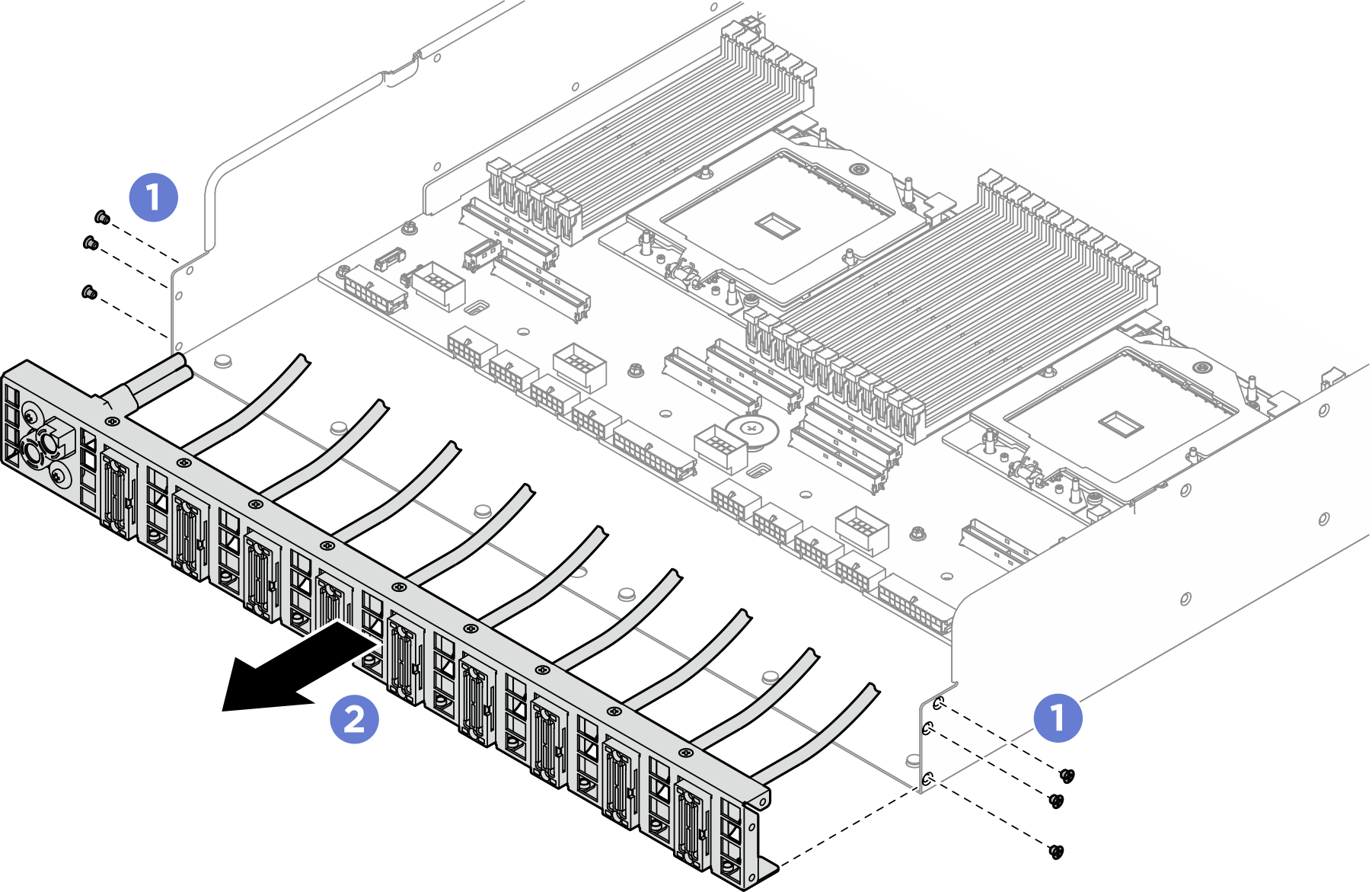
- If needed, remove the cables from the rear PCIe switch cable harness.
Front I/O module, integrated diagnostics panel, GPU management, or signal cable
- Unfasten the two screws that secure the bracket to the rear PCIe switch cable harness.
- Slide the bracket away from the rear PCIe switch cable harness.
 Remove the cable from the rear PCIe switch cable harness.Figure 2. Front I/O module, integrated diagnostics panel, GPU management, or signal cable removal
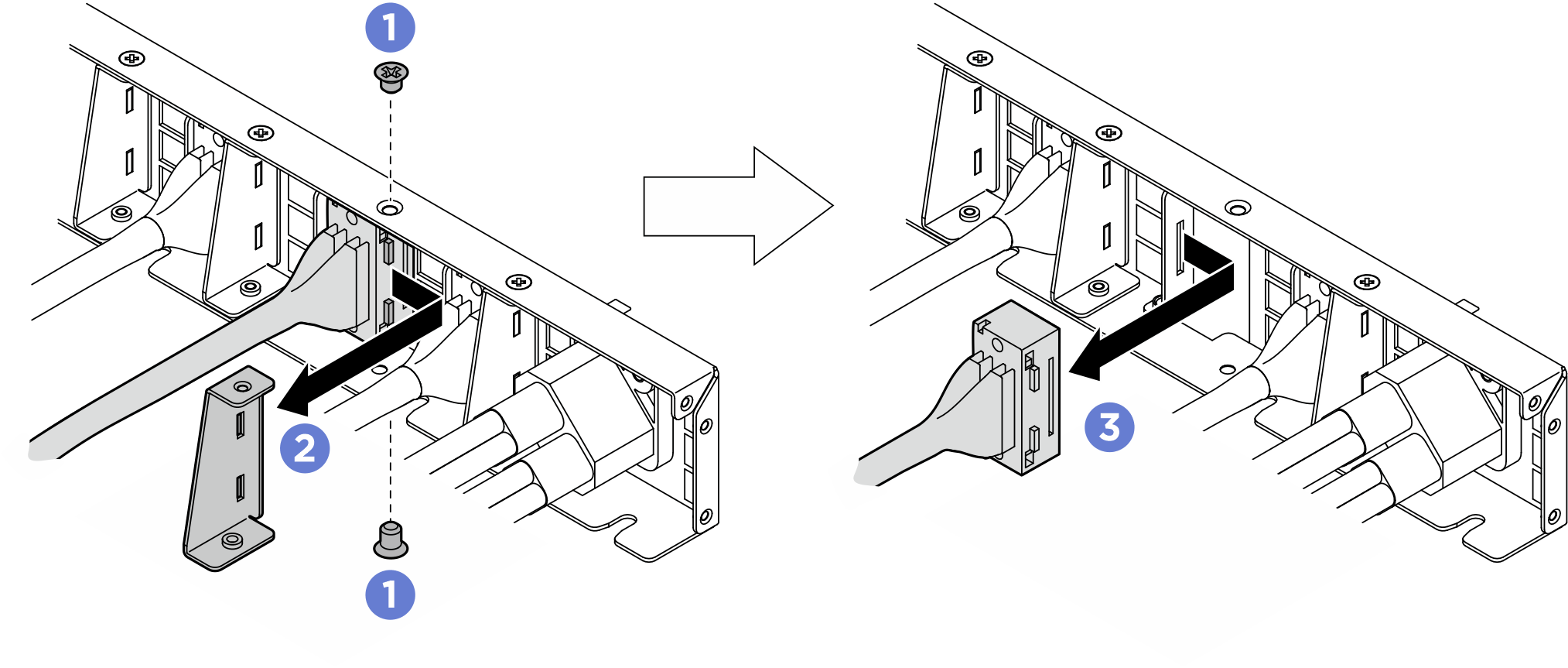
Power cable
- Remove the two screws and the two washers on the rear PCIe switch cable harness.
- Remove the cable from the rear PCIe switch cable harness.
Figure 3. Power cable removal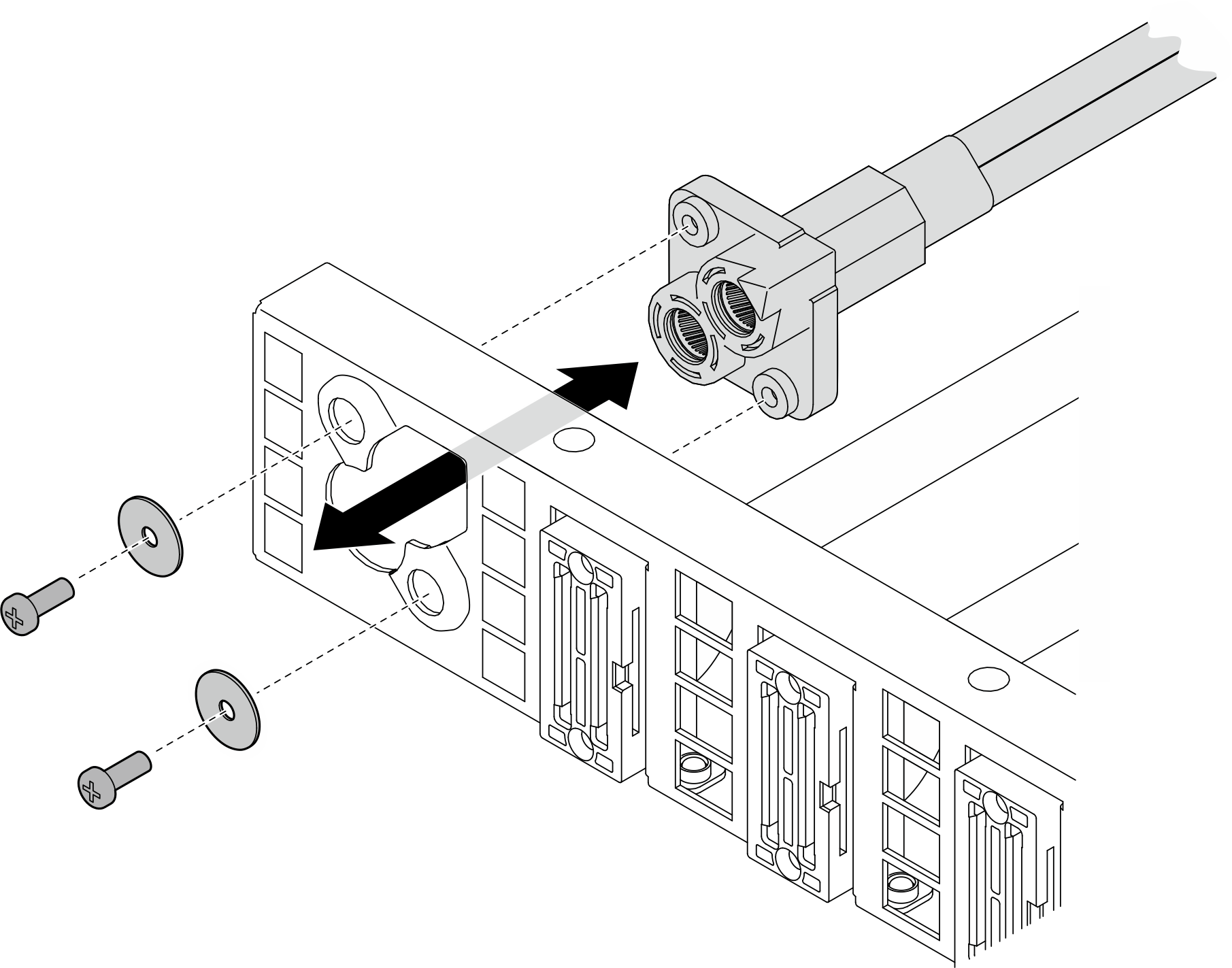
After you finish
If you are instructed to return the component or optional device, follow all packaging instructions, and use any packaging materials for shipping that are supplied to you.
Give documentation feedback