Remove the front PCIe switch cable harness
Follow instructions in this section to remove the front PCIe switch cable harness. The procedure must be executed by a trained technician.
About this task
Attention
- Read Installation Guidelines and Safety inspection checklist to ensure that you work safely.
- Power off the server and peripheral devices and disconnect the power cords and all external cables. See Power off the server.
- Two people and one lifting device on site that can support up to 400 lb (181 kg) are required to perform this procedure. If you do not already have a lifting device available, Lenovo offers the Genie Lift GL-8 material lift that can be purchased at Data Center Solution Configurator. Make sure to include the Foot-release brake and the Load Platform when ordering the Genie Lift GL-8 material lift.
Note
Make sure you have a 5 mm hex socket screwdriver available to properly replace the component:
Procedure
- Remove the front I/O module.
 Unfasten the two outer screws on the front I/O module.
 Unfasten the inner screw on the front I/O module.
 Slide the front I/O module rearward.
Figure 1. Front I/O module removal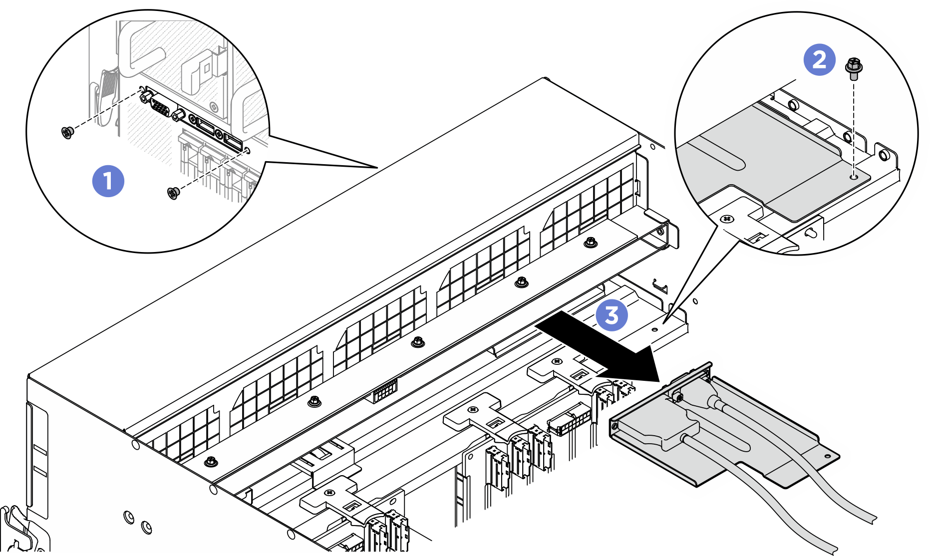
- Remove the following front I/O module cables.
- Unfasten the two hex nuts (1) to remove the VGA cable from the front I/O bracket.
- Unfasten the two screws (2) to remove the USB cable from the front I/O bracket.
Figure 2. Front I/O module cables removal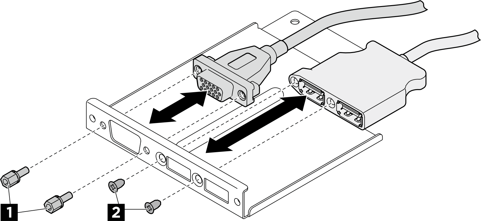
- Remove the front PCIe switch cable harness.
- Unfasten the ten screws marked with C on both sides of the 8U GPU shuttle.
- Lift the front PCIe switch cable harness out of the 8U GPU shuttle.
Figure 3. Front PCIe switch cable harness removal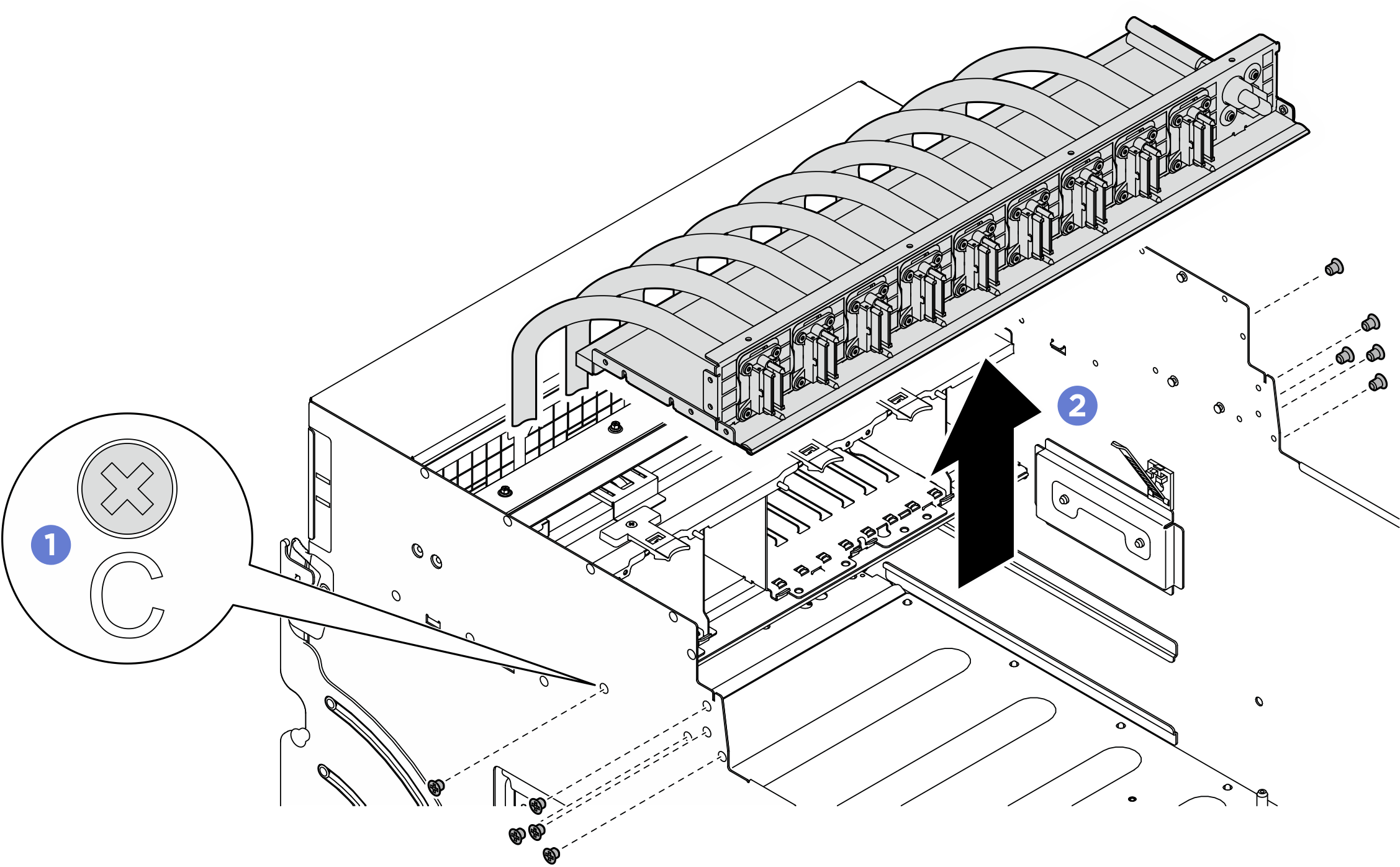
- If needed, remove the cables from the front PCIe switch cable harness.
Front I/O module, integrated diagnostics panel, GPU management, or signal cable
Unfasten the four screws to remove the cable from the front PCIe switch cable harness.
Figure 4. Front I/O module, integrated diagnostics panel, GPU management, or signal cable removal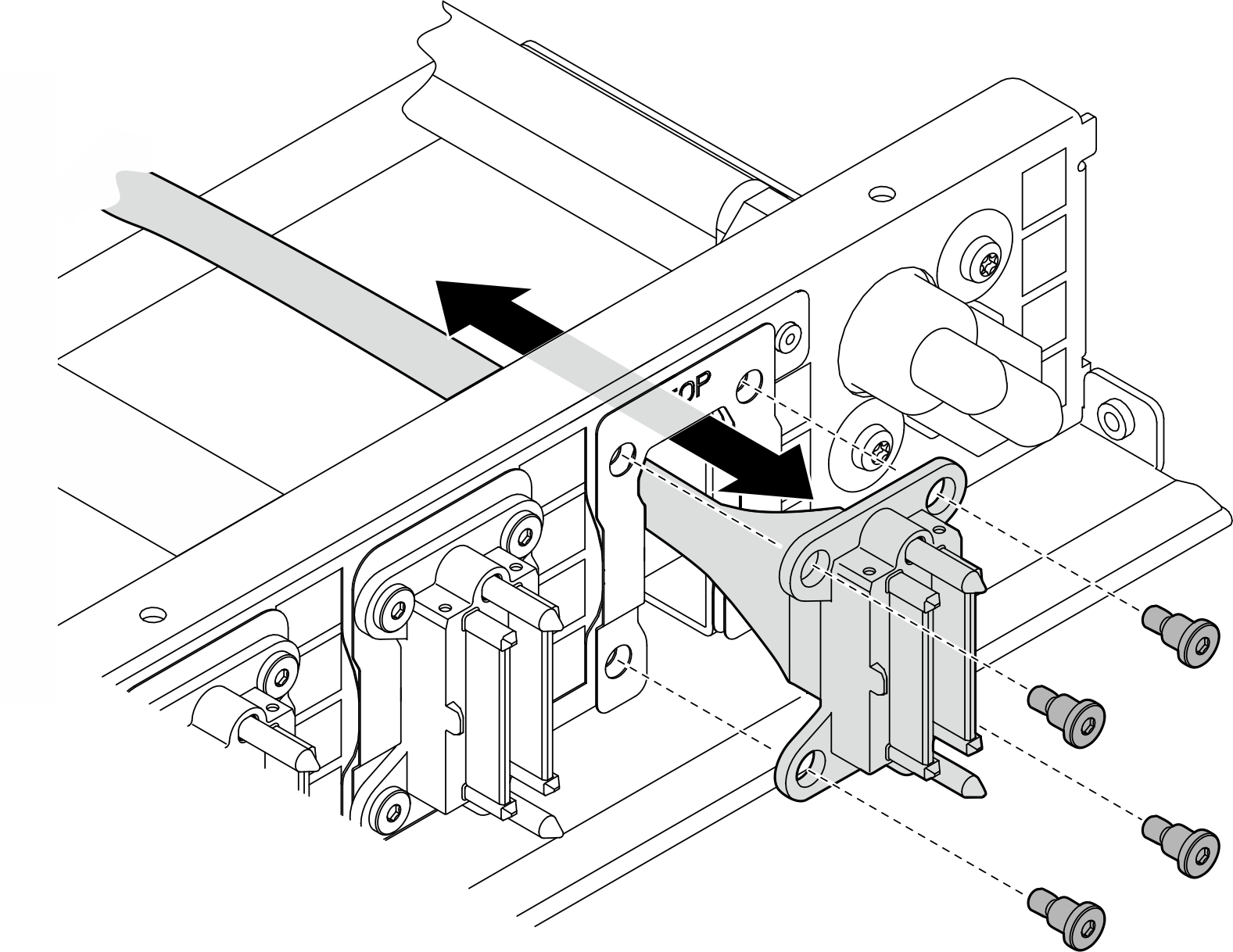
Power cable
- Remove the two screws and the two washers on the front PCIe switch cable harness.
- Remove the cable from the front PCIe switch cable harness.
Figure 5. Power cable removal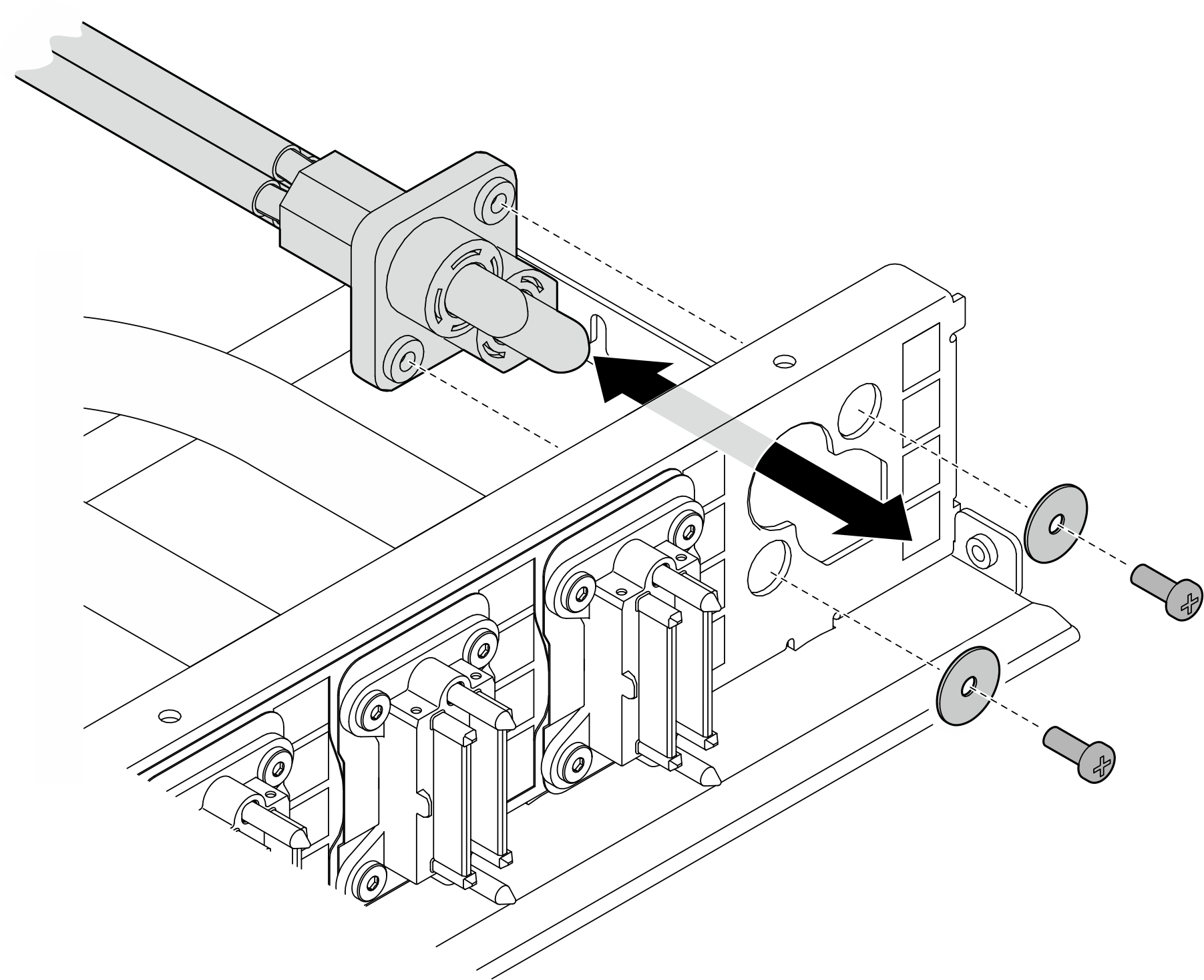
After you finish
If you are instructed to return the component or optional device, follow all packaging instructions, and use any packaging materials for shipping that are supplied to you.
Give documentation feedback