Instalación de la placa base de la GPU B200
Siga las instrucciones que aparecen en esta sección para instalar la placa base de la GPU B200. El procedimiento debe ser realizado por un técnico capacitado.
Acerca de esta tarea
Atención
- Lea Directrices de instalación y Lista de comprobación de inspección de seguridad para asegurarse de que trabaja con seguridad.
- Ponga en contacto la bolsa antiestática que contiene el componente con cualquier superficie metálica no pintada del servidor y, a continuación, quite el componente de la bolsa y colóquelo en una superficie antiestática.
- Asegúrese de inspeccionar los conectores y zócalos de la GPU y la placa base de la GPU. No utilice la GPU ni la placa base de la GPU si faltan sus conectores o estos están dañados ni tampoco si hay suciedad en los zócalos. Sustituya la GPU o la placa base de la GPU por una nueva antes de continuar con el procedimiento de instalación.
Nota
Asegúrese de que tiene a mano las herramientas requeridas que aparecen a continuación para sustituir correctamente el componente:
- Destornillador de cabeza Torx T15
- 2 brocas de extensión Torx T15 de 200mm
- Destornillador de cabeza Phillips n.° 1
- Destornillador de cabeza Phillips n.°2
- Toallita de limpieza con alcohol
- 2 PCM B200
- 2 PAD-1 SXM6 B200
- 2 PAD-2 SXM6 B200
- Kit de soporte de envío F&R de GPU B200
- Kit de servicio de GPU B200
- Kit de servicio del NVSwitch de retemporizador B200
- Kit de envío del NVSwitch de retemporizador B200
- PCM del NVSwitch B200
- PAD-1 del NVSwitch B200
- PAD-2 del NVSwitch B200
- Asa de la placa base de la GPU B200
- Broca de extensión Torx T25 de 150mm (para asas de placa base de GPU)
Nota
Asegúrese de que tiene a mano las herramientas requeridas que aparecen a continuación para sustituir correctamente el componente:
- Destornillador con regulación de par que se puede establecer en 0,6 newton-metros, 5,3 pulgadas-libras
Descarga de firmware y controlador: es posible que deba actualizar el firmware o el controlador después de sustituir un componente.
Vaya a Sitio web de descarga de controladores y software de ThinkSystem SR780a V3 para ver las actualizaciones más recientes de firmware y controlador para su servidor.
Acceda a Actualización del firmware para obtener más información sobre las herramientas de actualización de firmware.
En la siguiente ilustración, se muestra la numeración de la GPU B200 y la numeración de ranuras correspondiente en XCC.
Figura 1. Numeración de la GPU B200
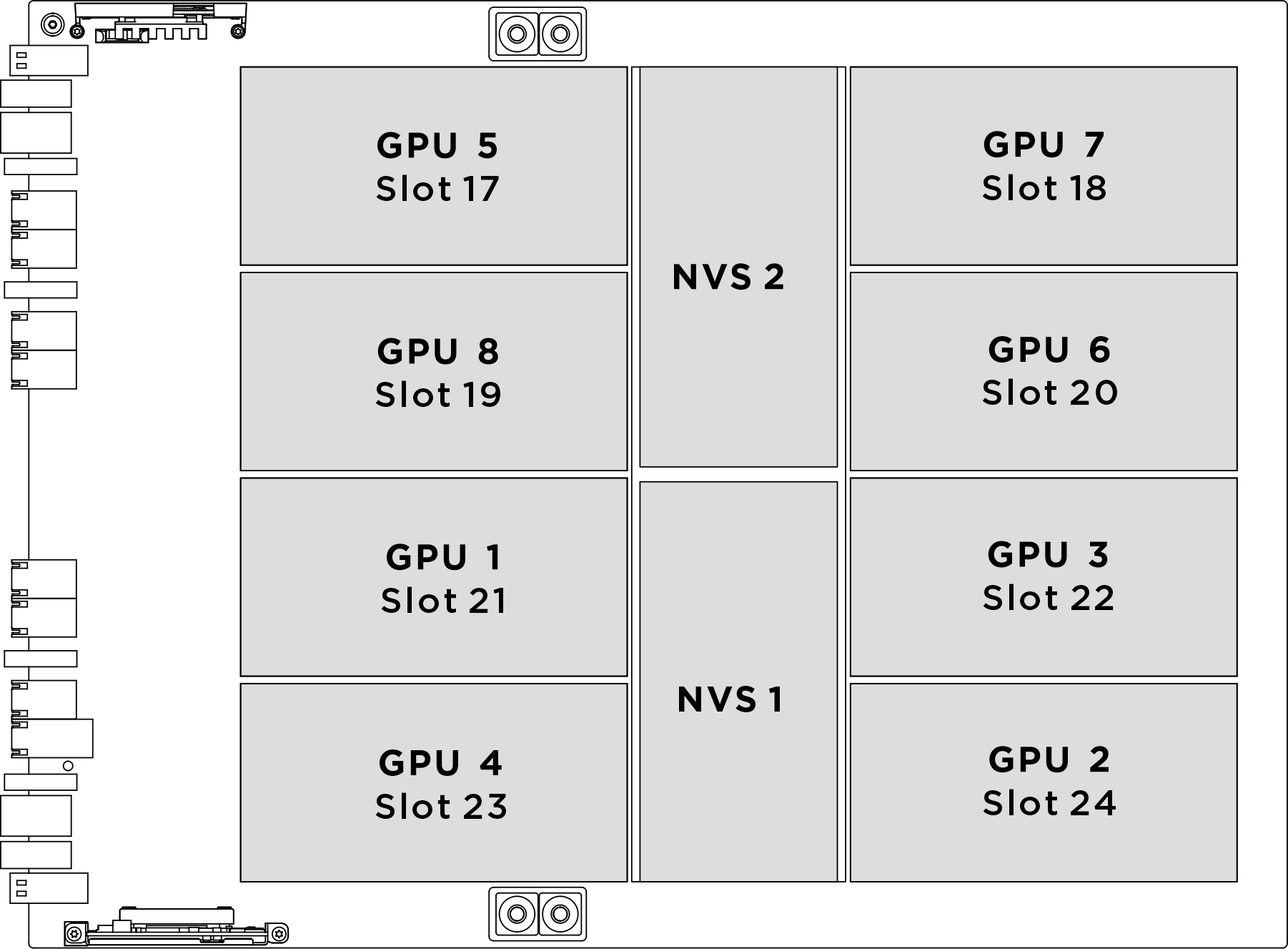
| Zócalo de GPU físico | Numeración de ranuras en XCC | Número lógico en nvidia-smi |
|---|---|---|
GPU 1 | Ranura 21 | 4 |
GPU 2 | Ranura 24 | 7 |
GPU 3 | Ranura 22 | 5 |
GPU 4 | Ranura 23 | 6 |
GPU 5 | Ranura 17 | 0 |
GPU 6 | Ranura 20 | 3 |
GPU 7 | Ranura 18 | 1 |
GPU 8 | Ranura 19 | 2 |
Procedimiento
- (Opcional) Quite la nueva placa base de GPU de la caja del paquete.
- Sostenga las dos asas y saque la placa base de la GPU de la caja del paquete.
Figura 2. Extracción de la placa base de GPU de la caja del paquete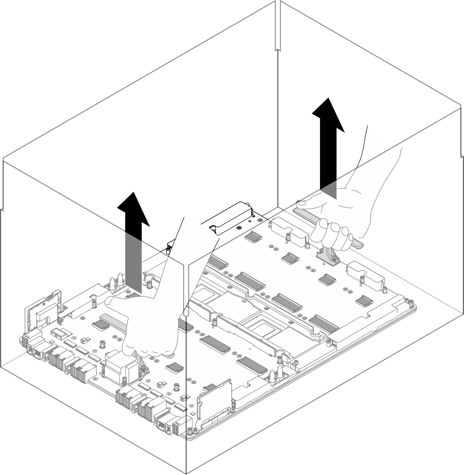
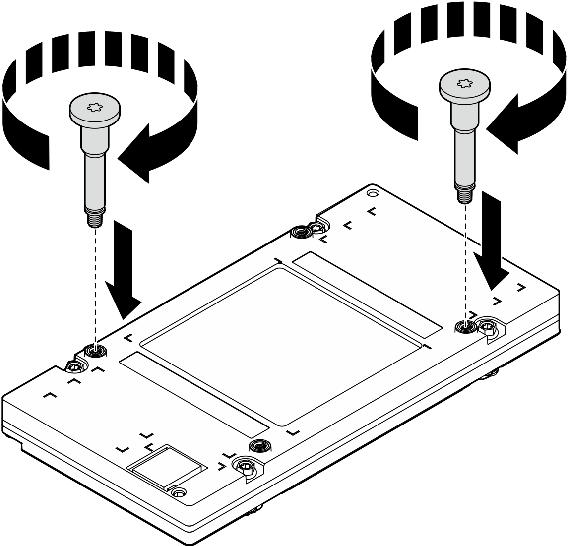
- Instale las GPU en la placa base de GPU. Utilice las asas roscadas de las GPU para instalar las GPU en la placa base y, a continuación, apriete simultáneamente los dos tornillos diagonales Torx T15 con el destornillador fijado en el par correspondiente.
- Instale las dos asas roscadas de la GPU en diagonal. Alinee las asas roscadas con los orificios de tornillos de la placa de frío y, luego, apriételas con la mano.Figura 3. Instalación de las asas roscadas de la GPU
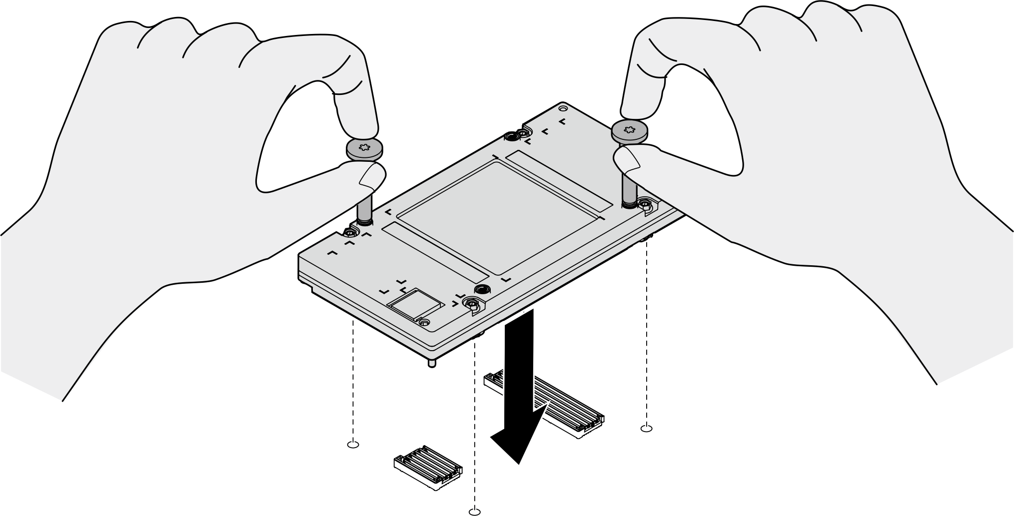
- Sostenga las asas roscadas de la GPU para colocarla con cuidado en la placa base de la GPU.Figura 4. Instalación de la GPU
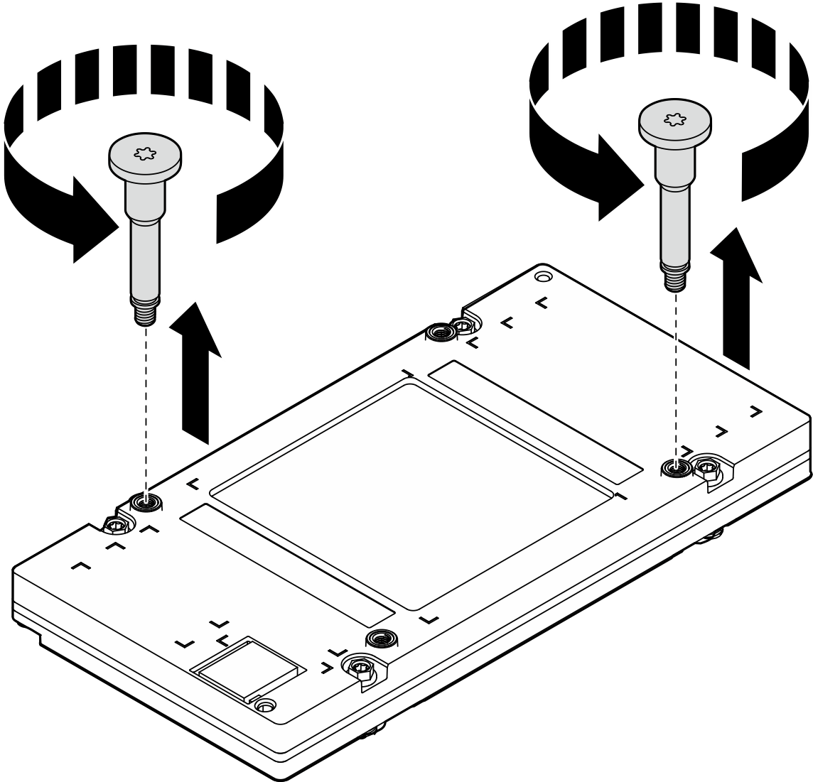
- Suelte con la mano las dos asas roscadas para quitarlas.Figura 5. Extracción de las asas roscadas de la GPU
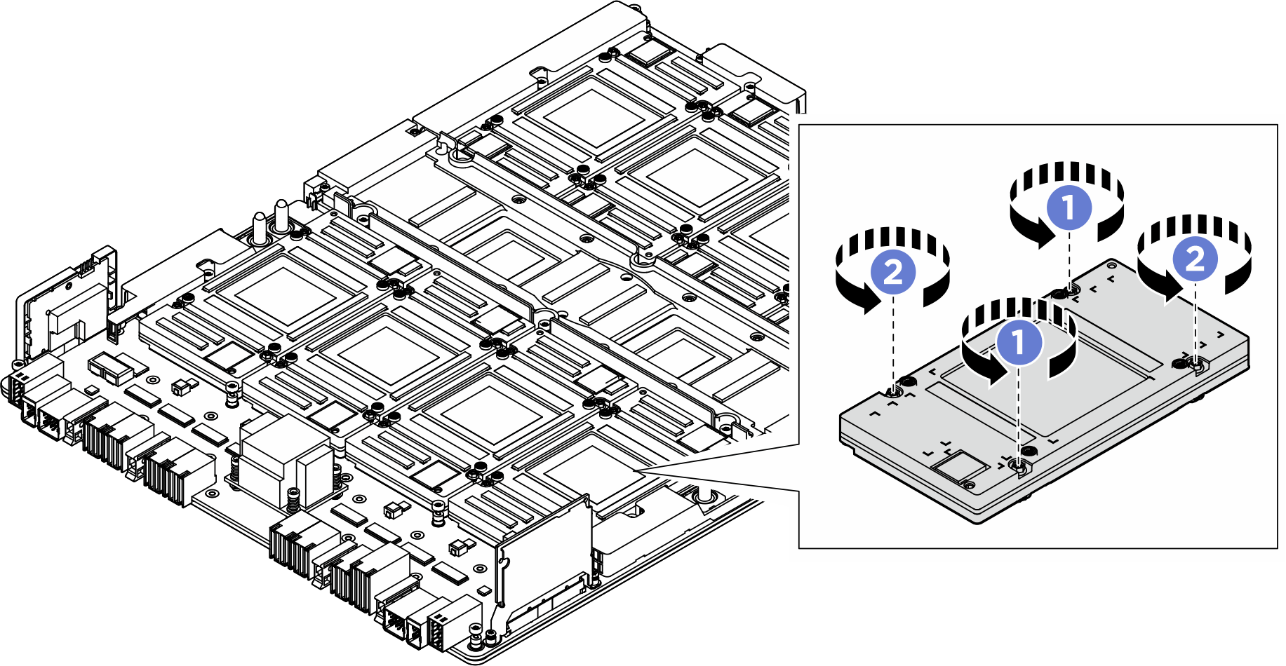
- Primero, ajuste el destornillador con regulación de par en 0,11±0,011 newton-metros, 0,97±0,097 pulgada-libras, para apretar simultáneamente los dos tornillos diagonales
 . Luego, apriete simultáneamente los dos tornillos diagonales
  .
. - Luego, ajuste el destornillador con regulación de par en 0,6±0,024 newton-metros, 5,3±0,212 pulgada-libras, para apretar simultáneamente los dos tornillos diagonales . Luego, apriete simultáneamente los dos tornillos diagonales .Figura 6. Instalación de la GPU
- Instale las dos asas roscadas de la GPU en diagonal. Alinee las asas roscadas con los orificios de tornillos de la placa de frío y, luego, apriételas con la mano.
- Instale el complejo de GPU.
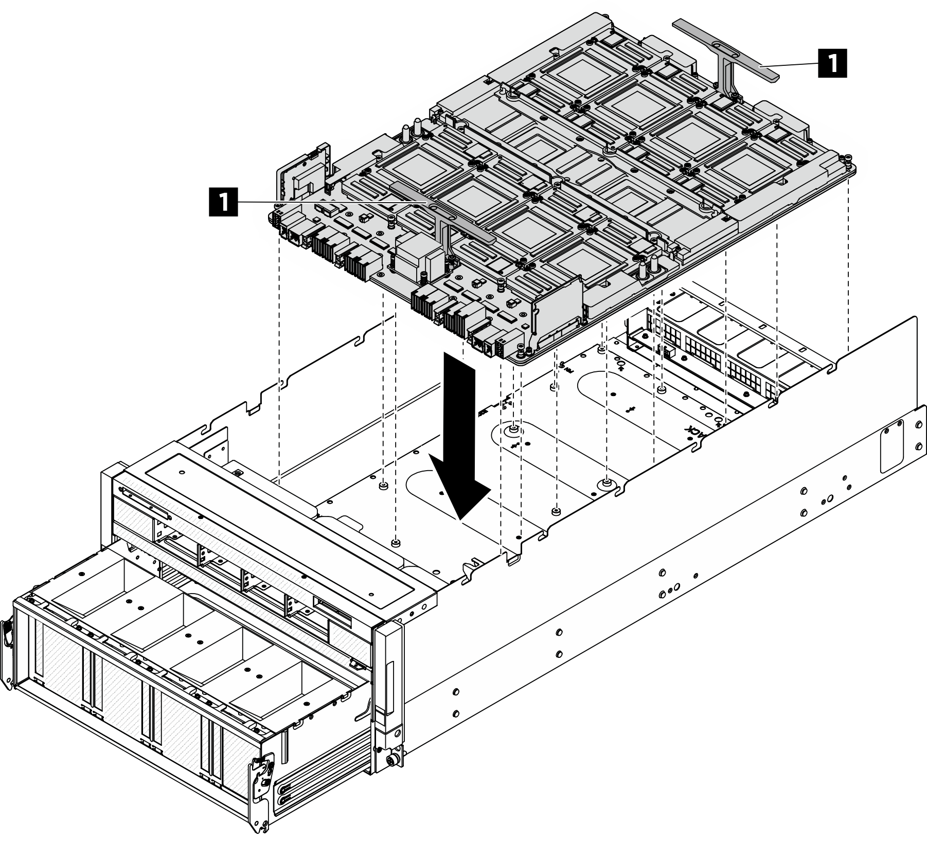
- Sostenga las asas (1) en ambos lados de la placa base de la GPU en la orientación correcta según la ilustración; luego, alinee el complejo de GPU con los diecisiete separadores en la placa del adaptador del complejo de GPU y colóquelo con cuidado en la placa del adaptador.Figura 7. Instalación del complejo de GPU
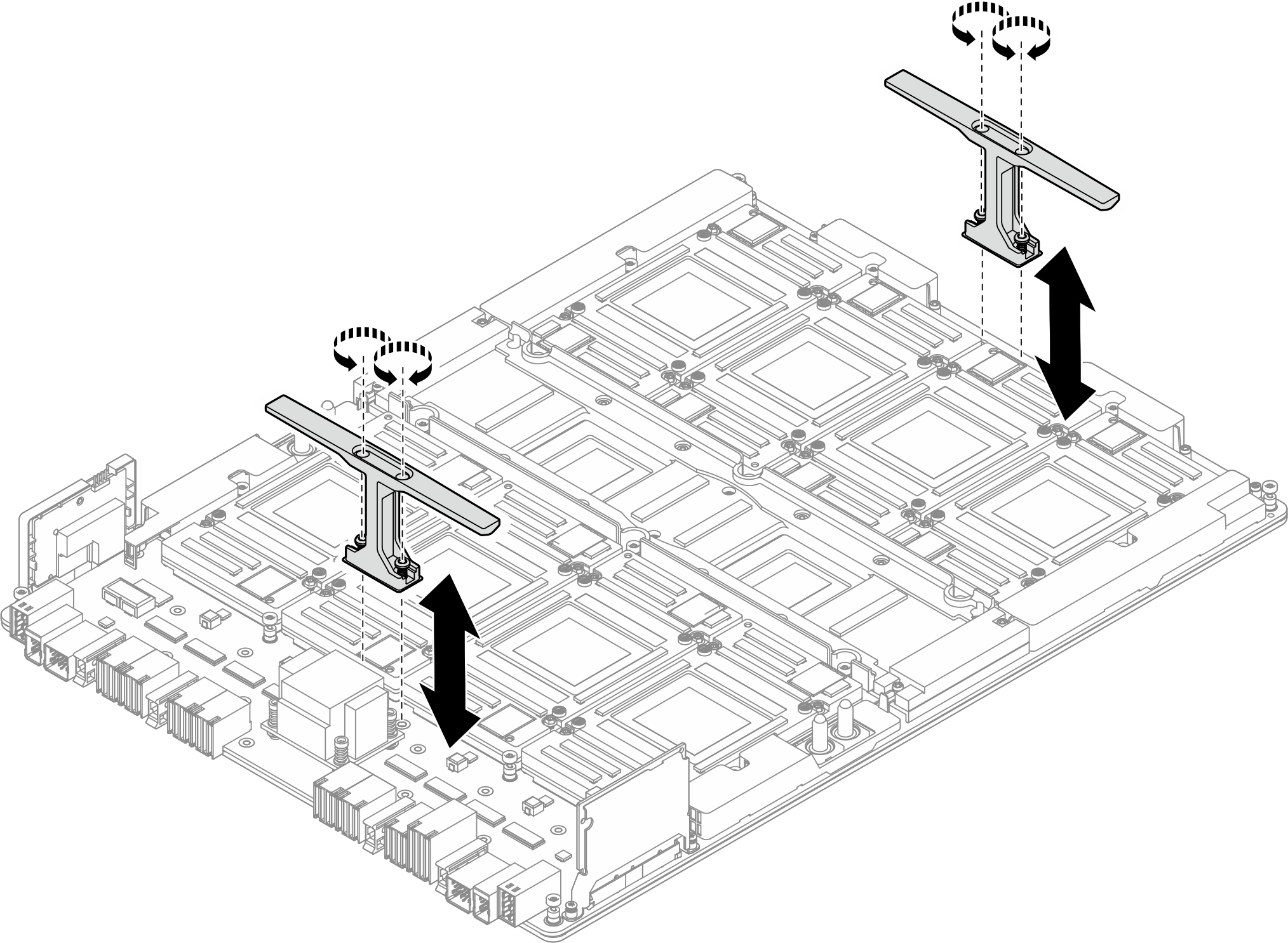
- Quite las asas. Coloque la broca de extensión Torx T25 al destornillador y suelte los cuatro tornillos M4 que fijan las asas al complejo de GPU. Luego, quite las asas del complejo de GPU.Figura 8. Extracción de las asas
 Siga la secuencia que se muestra en la siguiente ilustración para apretar los dieciocho tornillos de fijación Torx T15 para fijar el complejo de GPU.ImportanteNo ajuste de más los tornillos para evitar daños.NotaAfloje o apriete los tornillos con un destornillador de par con el par correspondiente. Como referencia, el par necesario para que los tornillos se suelten o aprieten completamente es de 0,6±0,024 newton-metros, 5,3±0,212 pulgada-libras.Figura 9. Instalación del tornillo
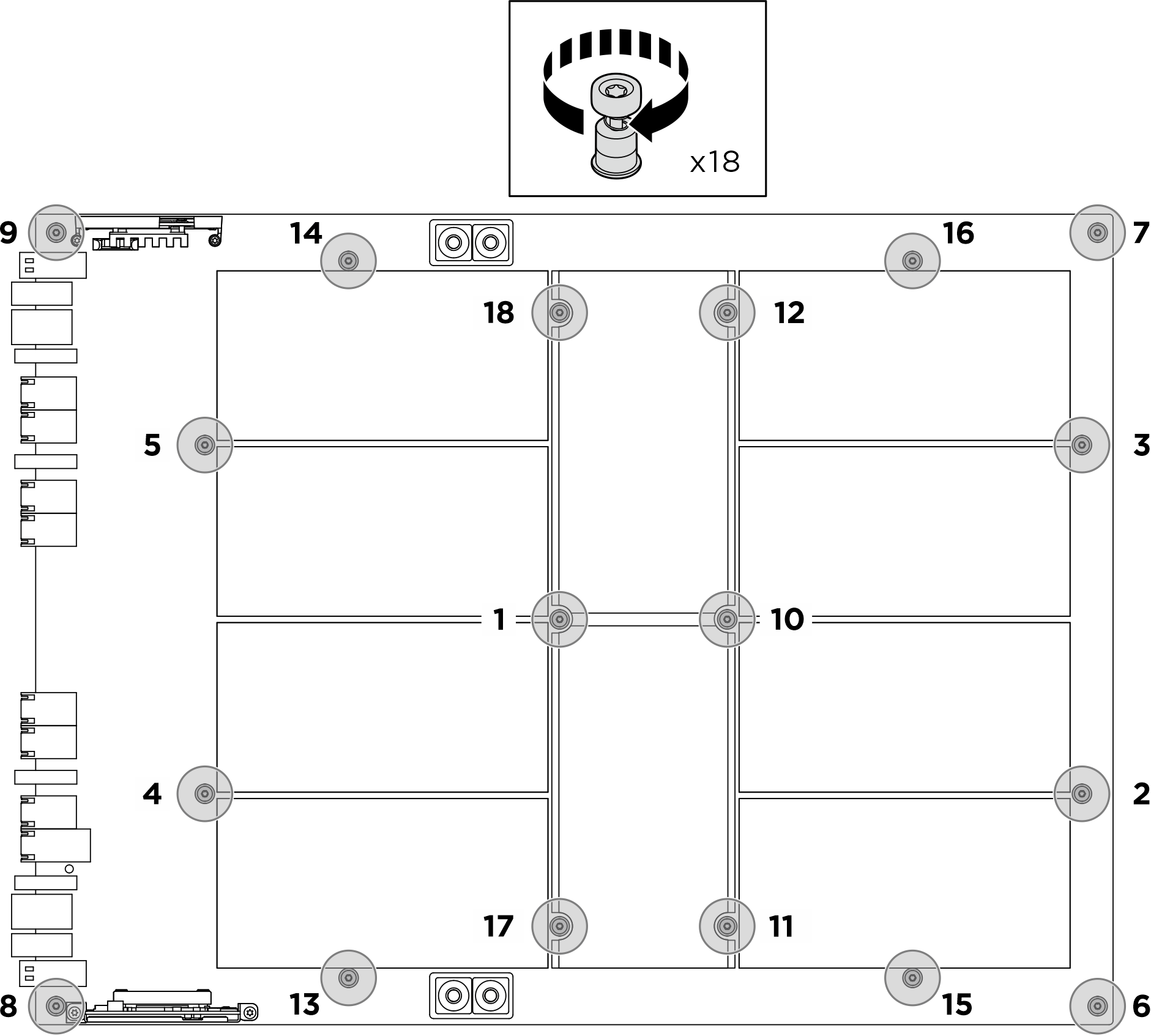
- Alinee la guía de la manguera con el orificio de tornillos del chasis; luego, apriete los tres tornillos M3 (PH2, 3 x M3, 0,5 newton-metros, 4,3 pulgada-libras) para fijar la guía de la manguera. Repita este proceso para instalar la guía de la manguera en el otro lado.Figura 10. Instalación de las guías de manguera

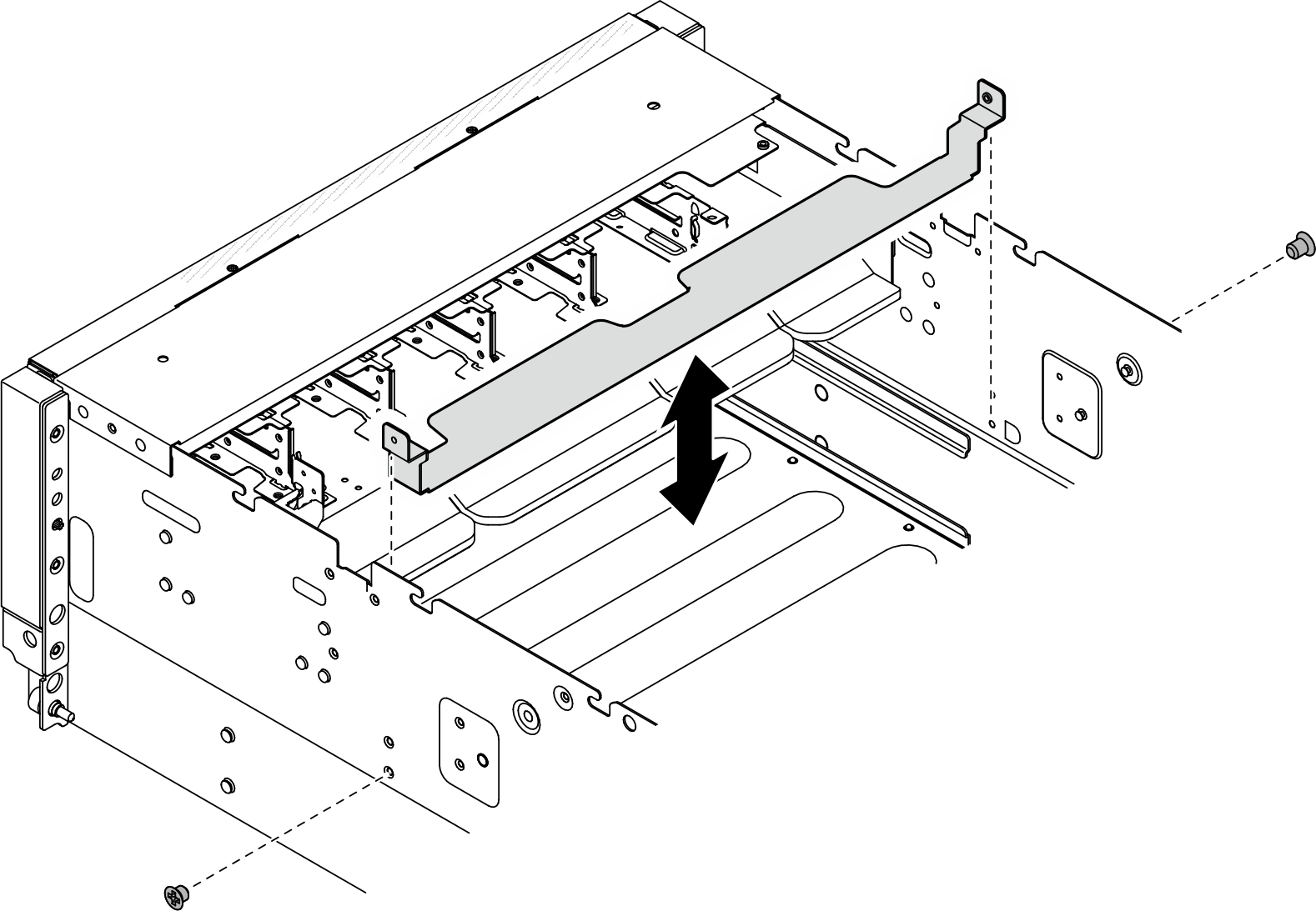
- Alinee el soporte protector de la tarjeta del adaptador CX-7 con los orificios de tornillos correspondiente; luego, apriete los dos tornillos M3 (PH2, 2 x M3, 0,5 newton-metros, 4,3 pulgada-libras) para fijar el soporte al chasis.Figura 11. Instalación del soporte protector de la tarjeta del adaptador CX-7
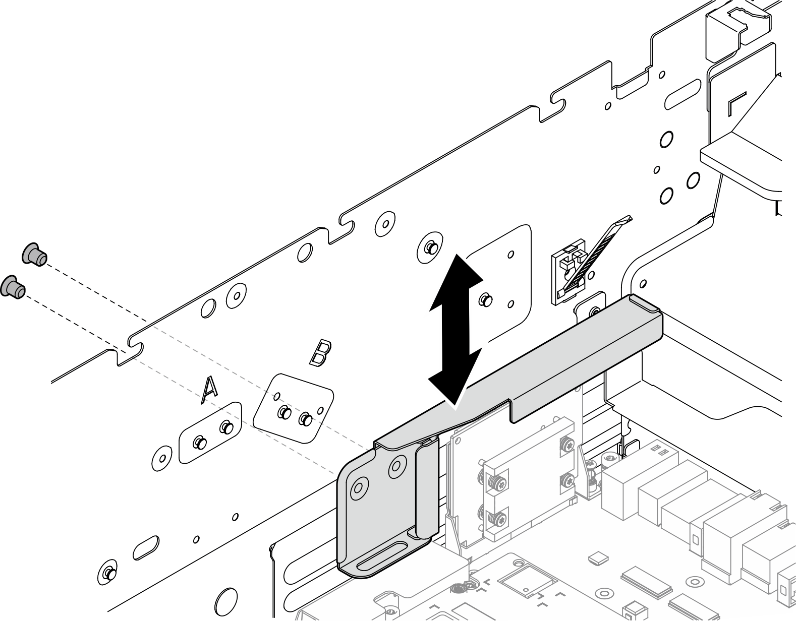
- Alinee el soporte protector del conector de la GPU con los orificios de tornillos correspondientes; luego, apriete los dos tornillos M3 (PH2, 2 x M3, 0,5 newton-metros, 4,3 pulgada-libras) para fijar el soporte protector del conector de la GPU al chasis.Figura 12. Instalación del soporte protector del conector de la GPU
- Instale la lanzadera del conmutador PCIe.
- Presione los dos pestillos de liberación azules.
- Presione los dos pestillos de bloqueo en ambos lados de la lanzadera del conmutador PCIe.
- Empuje la lanzadera del conmutador PCIe hacia el chasis hasta que se detenga.
 Gire las dos palancas de liberación hasta que se bloqueen en su lugar.Figura 13. Instalación de la lanzadera del conmutador PCIe
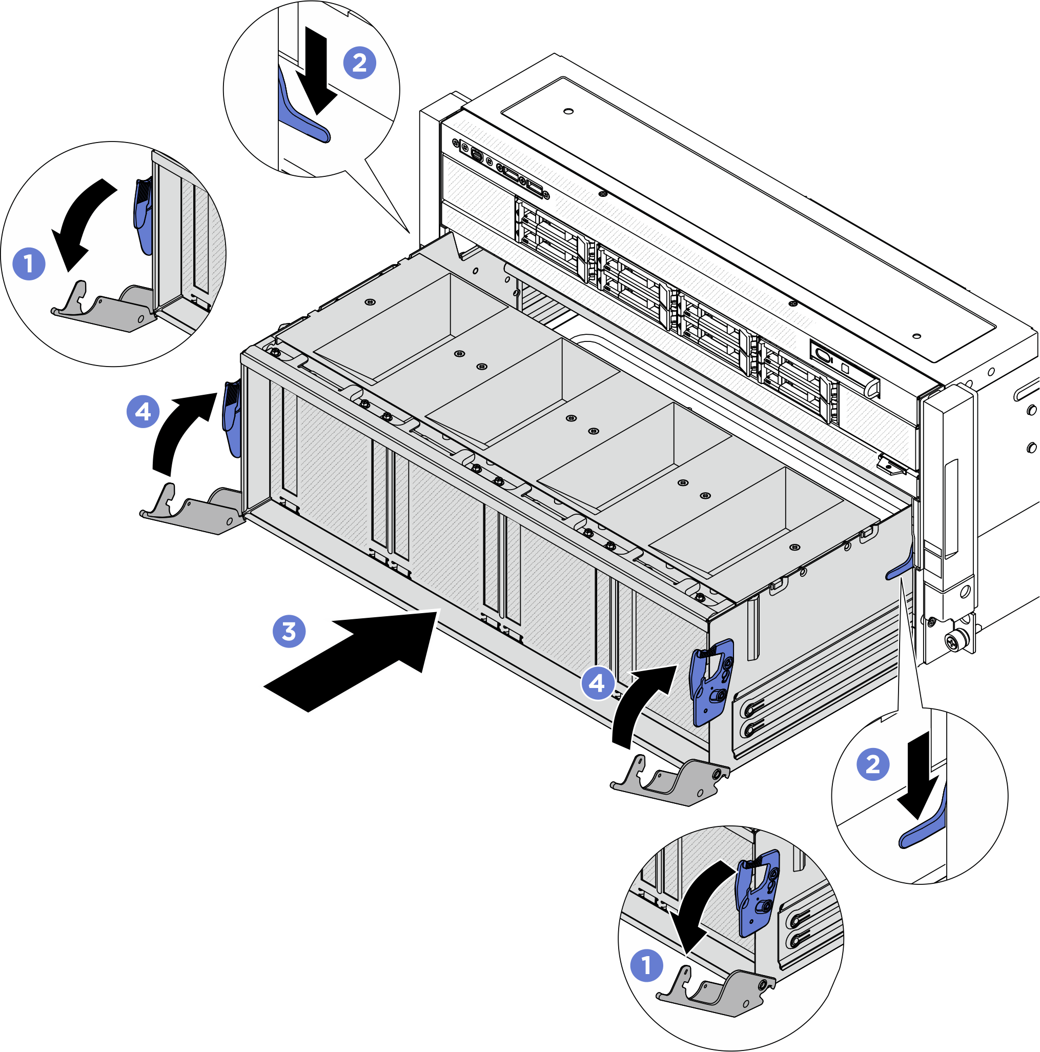
Después de finalizar
- Vuelva a instalar el módulo de la placa de frío del NVSwitch y el retemporizador. Consulte Instalación del módulo de la placa de frío del NVSwitch y el retemporizador B200.
- Vuelva a instalar el módulo de la placa de frío de la GPU B200 frontal. Consulte Instalación del módulo de la placa de frío de la GPU B200 frontal.
- Vuelva a instalar el módulo de la placa de frío de la GPU B200 posterior. Consulte Instalación del módulo de la placa de frío de la GPU B200 posterior.
- Vuelva a conectar los cables a la Placa base de GPU. Para obtener más información, consulte Disposición de los cables de la placa base de la GPU.
- Vuelva a conectar todos los cables que se desconectaron. Consulte Disposición interna de los cables.
- Vuelva a instalar el complejo de alimentación. Consulte Instalación del complejo de alimentación.
- Vuelva a instalar el complejo de CPU. Consulte Instalación del complejo de CPU.
- Vuelva a instalar el compartimiento del ventilador. Consulte Instalación del compartimiento del ventilador (solamente para técnicos capacitados).
- Vuelva a instalar la cubierta superior posterior. Consulte Instalación de la cubierta superior posterior.
- Vuelva a instalar la cubierta superior frontal. Consulte Instalación de la cubierta superior frontal.
- Complete la sustitución de piezas. Consulte Completar la sustitución de piezas.
Entregar comentarios