PCIe riser 1 cable routing
Follow the instructions in this section to learn how to do cable routing for the PCIe riser 1.
Note
- When routing the cables, ensure that all cables are routed appropriately through the cable guides and cable clips.
- A label on each signal cable indicates the connection source and destination. This information is in the format RY-X and P Z. Where Y indicates the PCIe riser number, X indicates the connector on the riser card, and Z indicates the connector on the system board assembly.
Choose the routing plan according to the PCIe riser type.
- See Two-slot PCIe HL riser 1 cable routing for the following PCIe riser:
- x16/x16 PCIe G5 Riser 1/3 FHFL (installed in the riser 1 without riser extender)
- See Two-slot PCIe FL riser 1 cable routing for the following PCIe riser:
- x16/x16 PCIe G5 Riser 1/3 FHFL (installed in the riser 1 with riser extender)
- See Two-slot PCIe HL riser 1 (with 7mm drive cage) cable routing for the following PCIe riser:
- 7mm/x16 PCIe G5 Riser 1 FHHL (without riser extender)
- See Two-slot PCIe FL riser 1 (with 7mm drive cage) cable routing for the following PCIe riser:
- 7mm/x16 PCIe G5 Riser 1 FHHL (with riser extender)
- See Three-slot PCIe HL riser 1 cable routing for the following PCIe riser:
- x8/x16/x16 PCIe G4 Riser 1/3 FHFL (installed in the riser 1 without riser extender)
- See Three-slot PCIe FL riser 1 cable routing for the following PCIe riser:
- x8/x16/x16 PCIe G4 Riser 1/3 FHFL (installed in the riser 1 with riser extender)
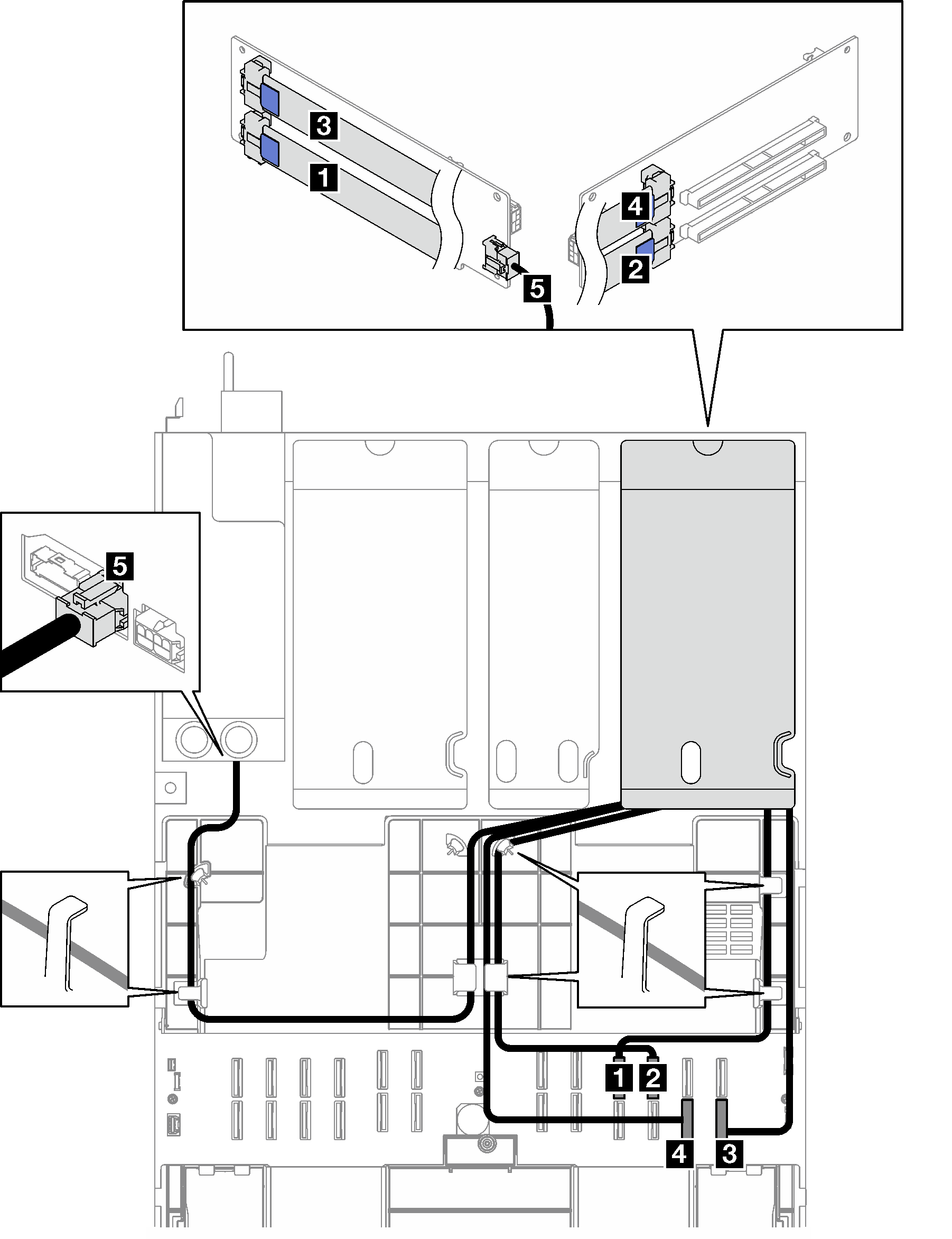
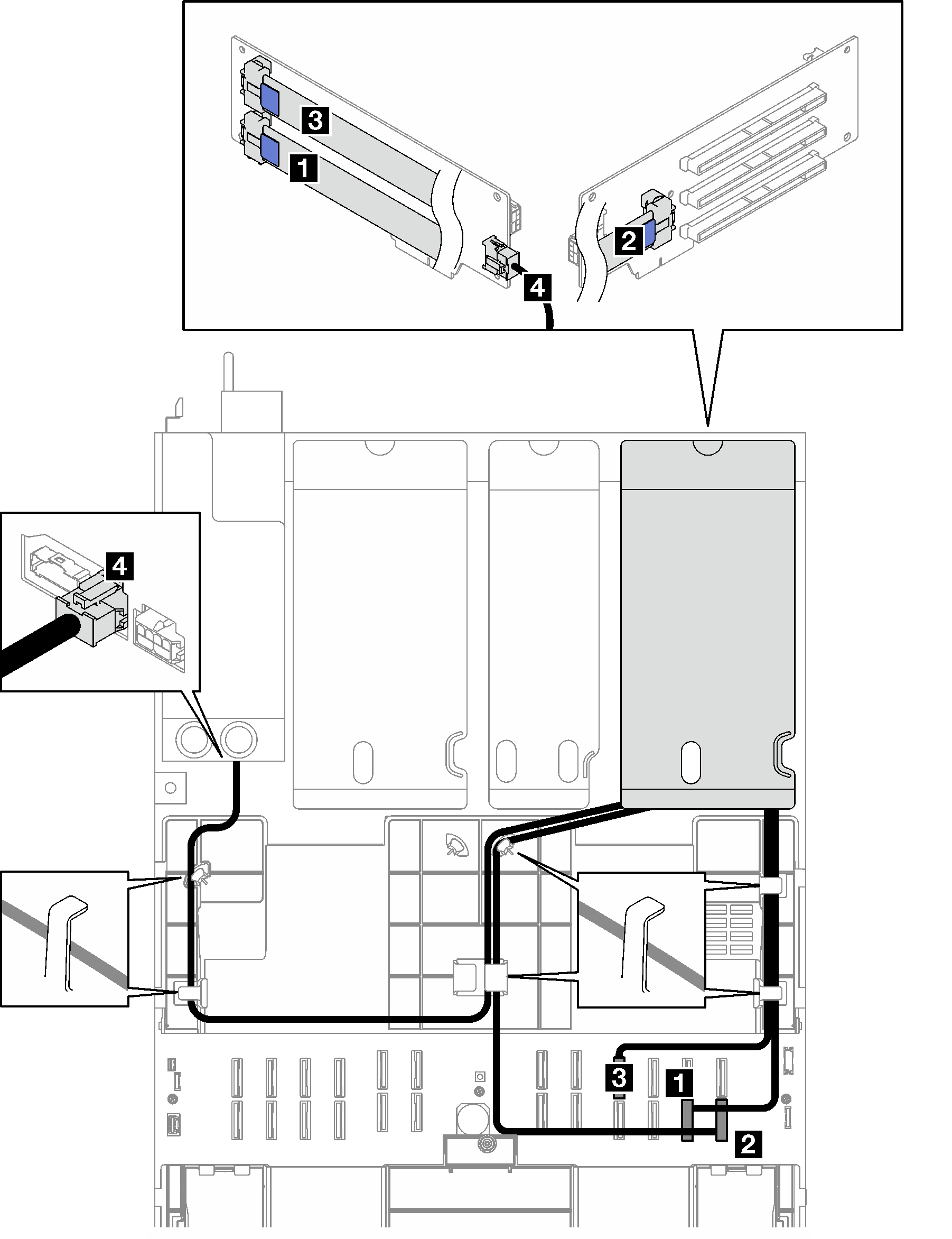
Two-slot PCIe HL riser 1 cable routing
The following illustration shows cable routing for the two-slot PCIe HL riser 1.
Figure 1. Cable routing for the two-slot PCIe HL riser 1
| Cable | From | To | Cable length | Label |
|---|---|---|---|---|
| 1 | PCIe riser 1: R1 connector | System board assembly: P 19 connector | 540 mm | R1-1 |
| P 19 | ||||
| 2 | PCIe riser 1: R2 connector | System board assembly: P 20 connector | 420 mm | R1-2 |
| P 20 | ||||
| 3 | PCIe riser 1: R3 connector | System board assembly: P 12 connector | 540 mm | R1-3 |
| P 12 | ||||
| 4 | PCIe riser 1: R4 connector | System board assembly: P 11 connector | 420 mm | R1-4 |
| P 11 | ||||
| 5 | PCIe riser 1: Riser power connector | Power distribution board: PCIe riser 1 power connector | 660 mm | N/A |
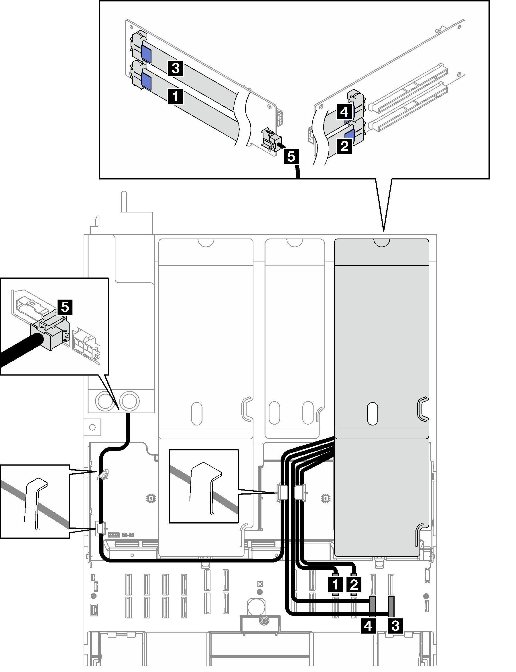
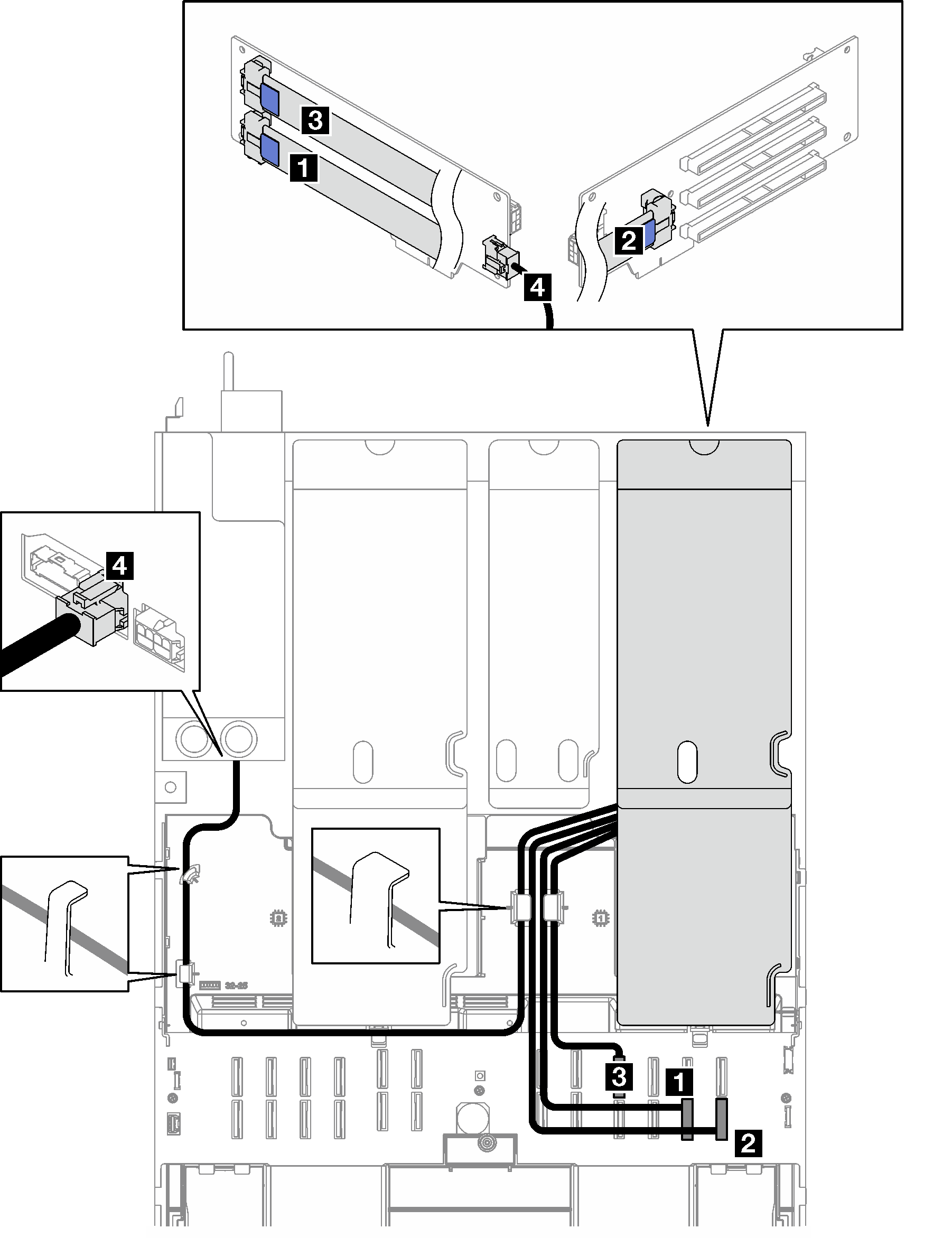
Two-slot PCIe FL riser 1 cable routing
The following illustration shows cable routing for the two-slot PCIe FL riser 1.
Figure 2. Cable routing for the two-slot PCIe FL riser 1
| Cable | From | To | Cable length | Label |
|---|---|---|---|---|
| 1 | PCIe riser 1: R1 connector | System board assembly: P 19 connector | 500 mm | R1-1 |
| P 19 | ||||
| 2 | PCIe riser 1: R2 connector | System board assembly: P 20 connector | 420 mm | R1-2 |
| P 20 | ||||
| 3 | PCIe riser 1: R3 connector | System board assembly: P 12 connector | 500 mm | R1-3 |
| P 12 | ||||
| 4 | PCIe riser 1: R4 connector | System board assembly: P 11 connector | 420 mm | R1-4 |
| P 11 | ||||
| 5 | PCIe riser 1: Riser power connector | Power distribution board: PCIe riser 1 power connector | 660 mm | N/A |
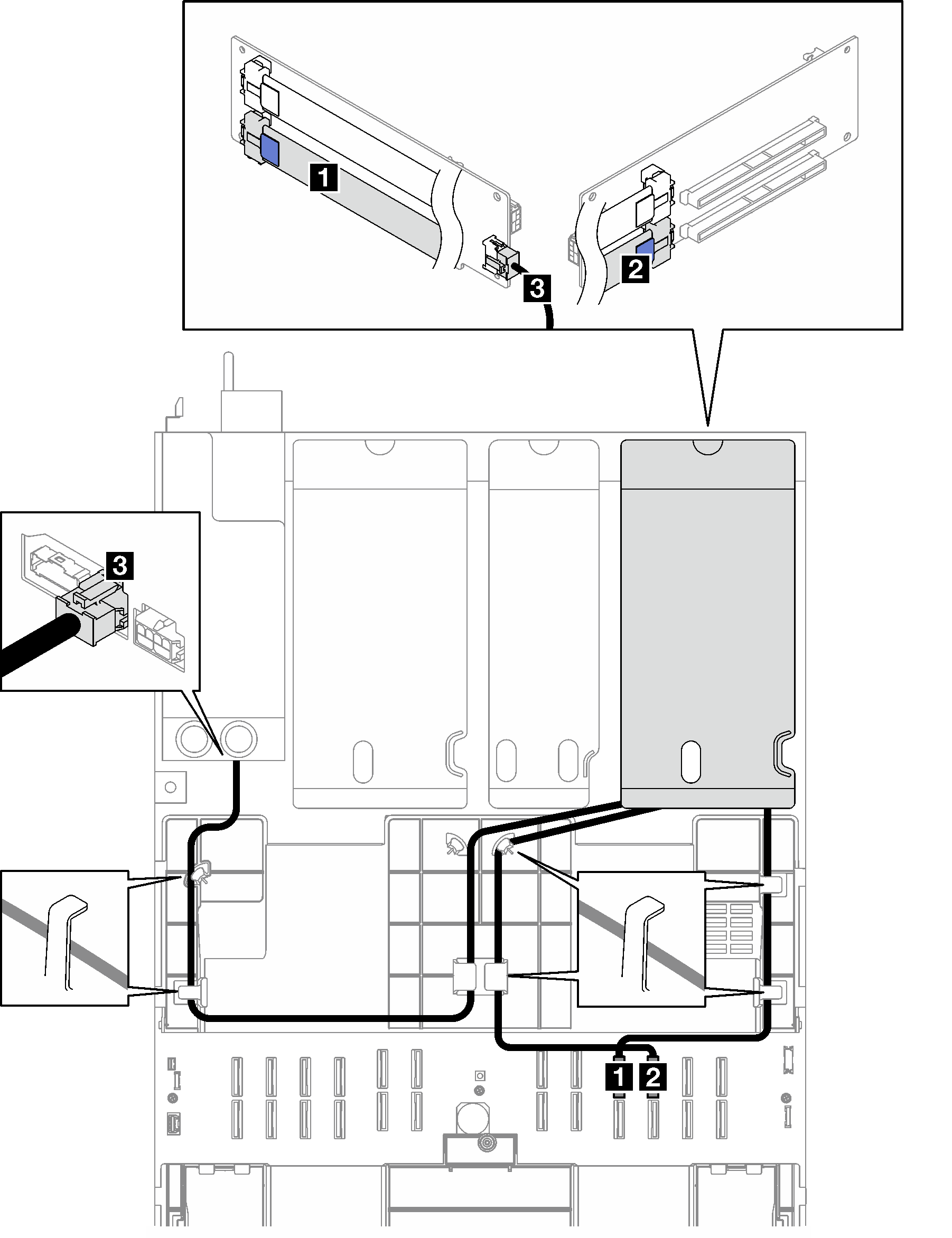
Two-slot PCIe HL riser 1 (with 7mm drive cage) cable routing
The following illustration shows cable routing for the two-slot PCIe HL riser 1 (with 7mm drive cage).
Figure 3. Cable routing for the two-slot PCIe HL riser 1 (with 7mm drive cage)
| Cable | From | To | Cable length | Label |
|---|---|---|---|---|
| 1 | PCIe riser 1: R1 connector | System board assembly: P 19 connector | 540 mm | R1-1 |
| P 19 | ||||
| 2 | PCIe riser 1: R2 connector | System board assembly: P 20 connector | 420 mm | R1-2 |
| P 20 | ||||
| 3 | PCIe riser 1: Riser power connector | Power distribution board: PCIe riser 1 power connector | 660 mm | N/A |
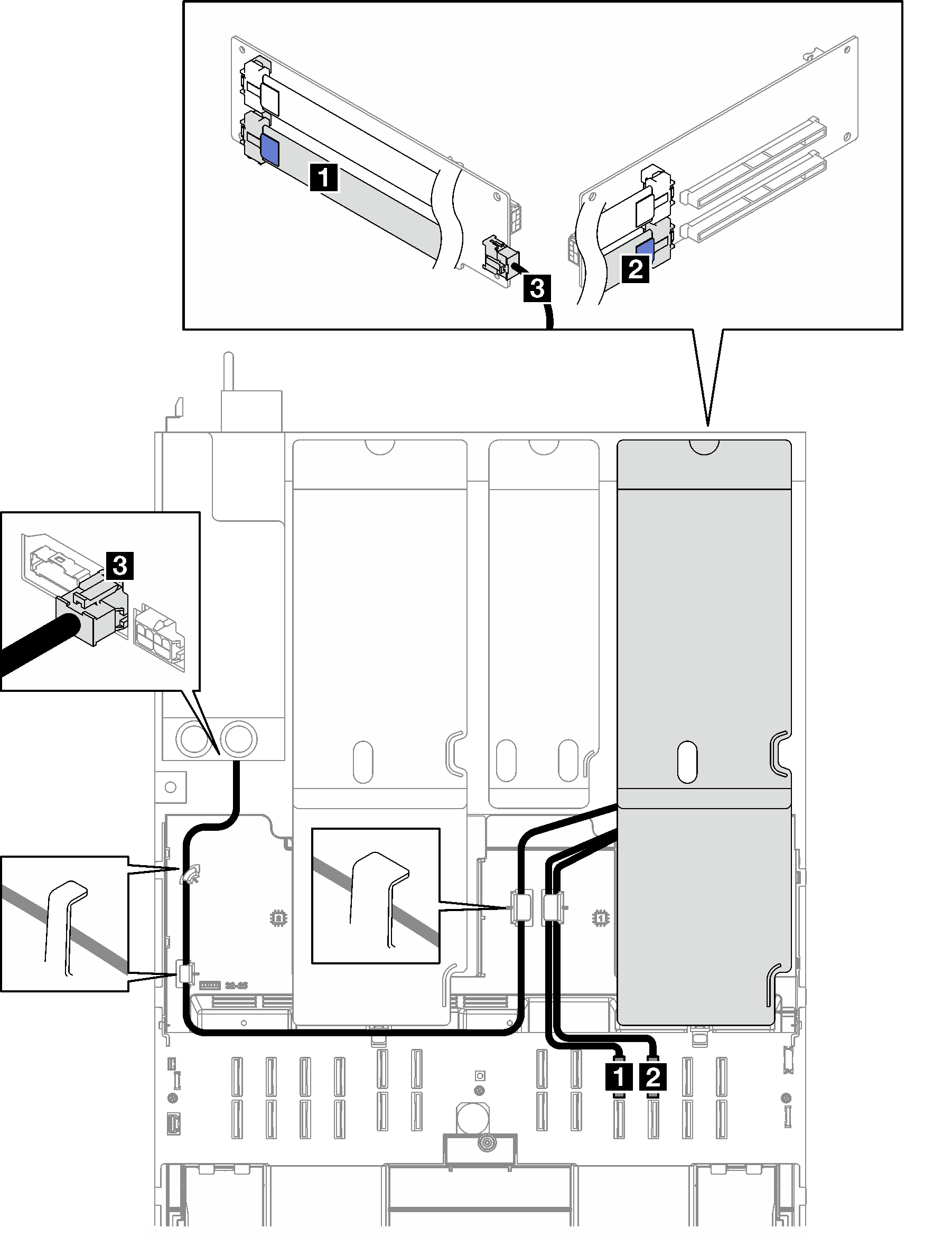
Two-slot PCIe FL riser 1 (with 7mm drive cage) cable routing
The following illustration shows cable routing for the two-slot PCIe FL riser 1 (with 7mm drive cage).
Figure 4. Cable routing for the two-slot PCIe FL riser 1 (with 7mm drive cage)
| Cable | From | To | Cable length | Label |
|---|---|---|---|---|
| 1 | PCIe riser 1: R1 connector | System board assembly: P 19 connector | 500 mm | R1-1 |
| P 19 | ||||
| 2 | PCIe riser 1: R2 connector | System board assembly: P 20 connector | 420 mm | R1-2 |
| P 20 | ||||
| 3 | PCIe riser 1: Riser power connector | Power distribution board: PCIe riser 1 power connector | 660 mm | N/A |
Three-slot PCIe HL riser 1 cable routing
The following illustration shows cable routing for the three-slot PCIe HL riser 1.
Figure 5. Cable routing for the three-slot PCIe HL riser 1
| Cable | From | To | Cable length | Label |
|---|---|---|---|---|
| 1 | PCIe riser 1: R1 connector | System board assembly: P 11 connector | 540 mm | R1-1 |
| P 11 | ||||
| 2 | PCIe riser 1: R2 connector | System board assembly: P 12 connector | 420 mm | R1-2 |
| P 12 | ||||
| 3 | PCIe riser 1: R3 connector | System board assembly: P 19 connector | 540 mm | R1-3 |
| P 19 | ||||
| 4 | PCIe riser 1: Riser power connector | Power distribution board: PCIe riser 1 power connector | 660 mm | N/A |
Three-slot PCIe FL riser 1 cable routing
The following illustration shows cable routing for the three-slot PCIe FL riser 1.
Figure 6. Cable routing for the three-slot PCIe FL riser 1
| Cable | From | To | Cable length | Label |
|---|---|---|---|---|
| 1 | PCIe riser 1: R1 connector | System board assembly: P 11 connector | 500 mm | R1-1 |
| P 11 | ||||
| 2 | PCIe riser 1: R2 connector | System board assembly: P 12 connector | 420 mm | R1-2 |
| P 12 | ||||
| 3 | PCIe riser 1: R3 connector | System board assembly: P 19 connector | 500 mm | R1-3 |
| P 19 | ||||
| 4 | PCIe riser 1: Riser power connector | Power distribution board: PCIe riser 1 power connector | 660 mm | N/A |
Give documentation feedback