M.2 backplane cable routing
Follow the instructions in this section to learn how to do cable routing for the M.2 backplane.
Note
When routing the cables, ensure that all cables are routed appropriately through the cable guides and cable clips.
SATA/NVMe or NVMe M.2 backplane
Figure 1. Cable routing for the SATA/NVMe or NVMe M.2 backplane
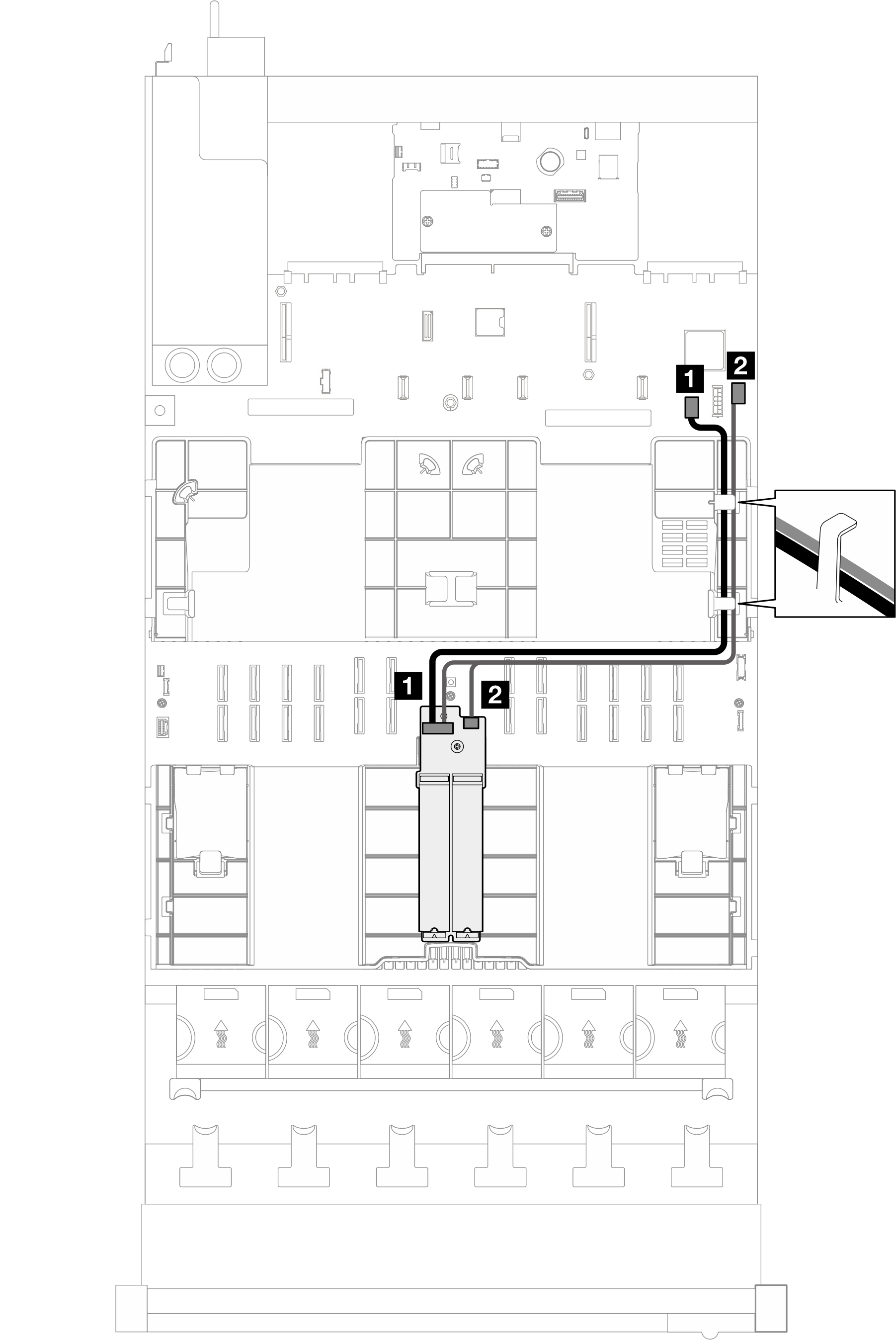
Note
This configuration supports non-RAID SATA, SATA RAID (VROC), non-RAID NVMe, and NVMe RAID (VROC standard).
| Cable | From | To | Cable |
|---|---|---|---|
| 1 | M.2 backplane: Signal connector | System board assembly: M.2 signal connector | M.2 signal and power cables (530/550/550 mm) |
| 2 | M.2 backplane: Power connector | System board assembly: M.2 power connector |
SATA/x4 NVMe M.2 backplane
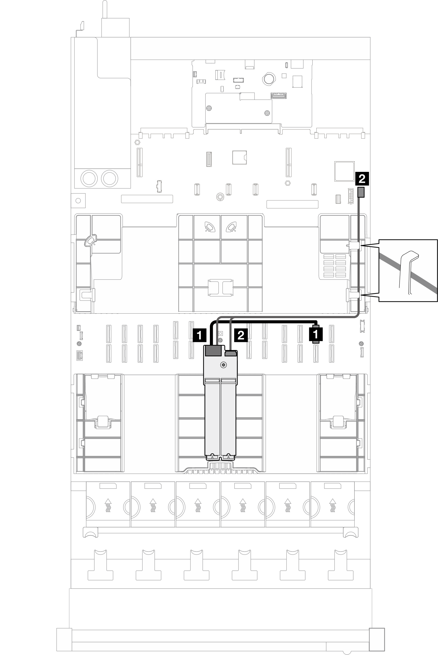
Figure 2. Cable routing for the SATA/x4 NVMe M.2 backplane to PCH
Note
This configuration supports non-RAID SATA and SATA RAID (VROC).
| Cable | From | To | Cable |
|---|---|---|---|
| 1 | M.2 backplane: Signal connector | System board assembly: M.2 signal connector | SlimSAS x4 to SlimSAS x8 cable (530 mm) |
| 2 | M.2 backplane: Power connector | System board assembly: M.2 power connector | Power 2x10 to power 2x10 (500 mm) |
Figure 3. Cable routing for the SATA/x4 NVMe M.2 backplane to processor
Note
This configuration supports non-RAID NVMe and NVMe RAID (VROC standard).
| Cable | From | To | Cable |
|---|---|---|---|
| 1 | M.2 backplane: Signal connector | System board assembly: NVMe 11 connector | MCIO x8 to SlimSAS x8 (365 mm) |
| 2 | M.2 backplane: Power connector | System board assembly: M.2 power connector | Power 2x10 to power 2x10 (500 mm) |
RAID SATA/NVMe M.2 backplane
Figure 4. Cable routing for the RAID SATA/NVMe M.2 backplane
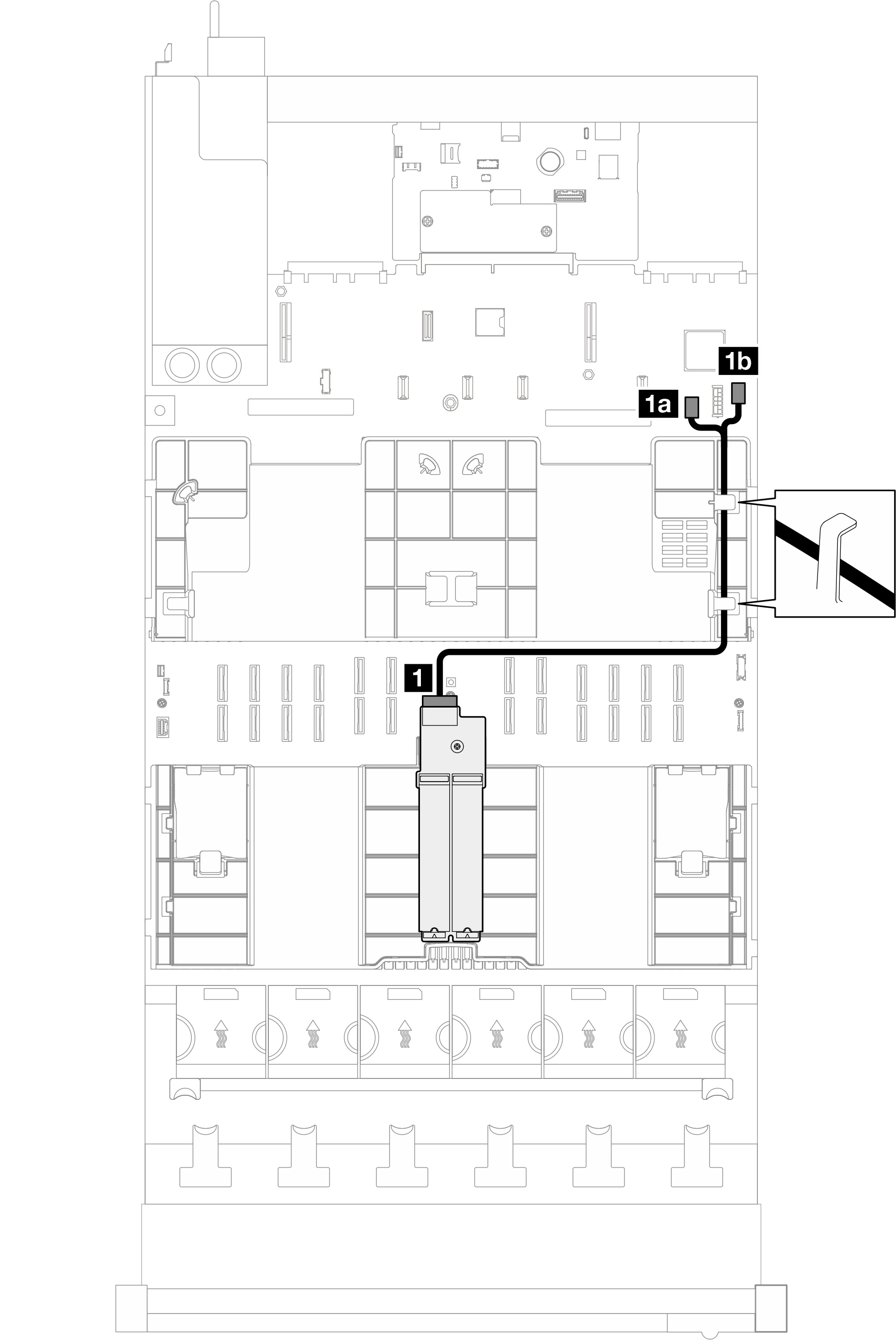
| Cable | From | To | Cable |
|---|---|---|---|
| 1 | M.2 backplane | 1a System board assembly: M.2 signal connector | M.2 signal and power cables (530/550 mm) |
| 1b System board assembly: M.2 power connector |
Give documentation feedback