Cable routing for 2.5-inch drives
Use this section to understand how to route cables for 2.5-inch drives.
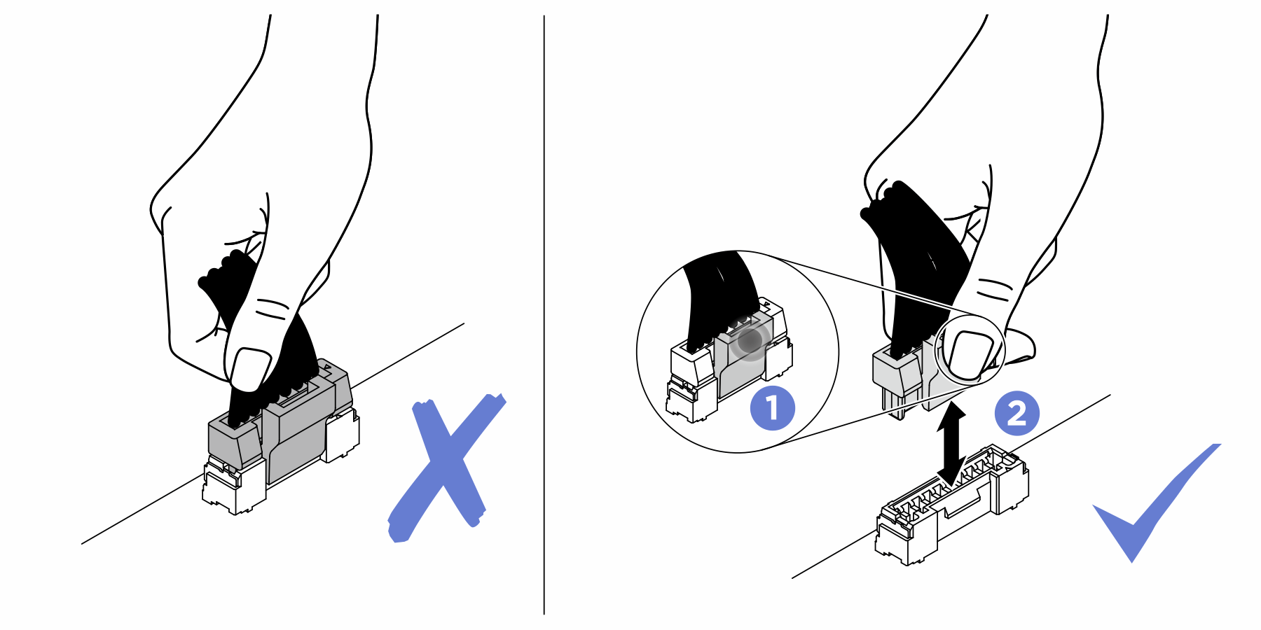
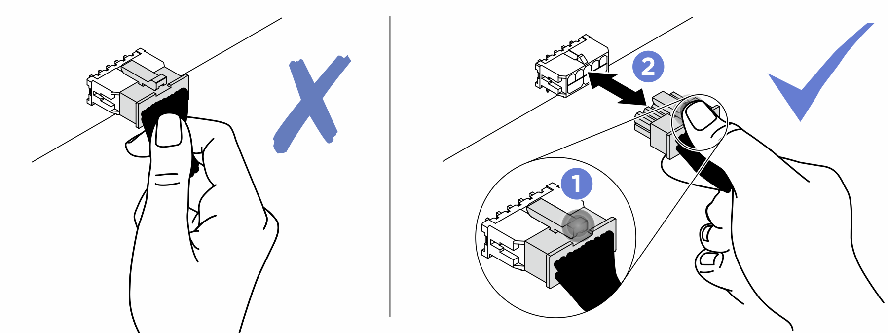
Connect cable connectors vertically or horizontally in alignment with the orientations of the corresponding cable sockets, avoiding any tilt.
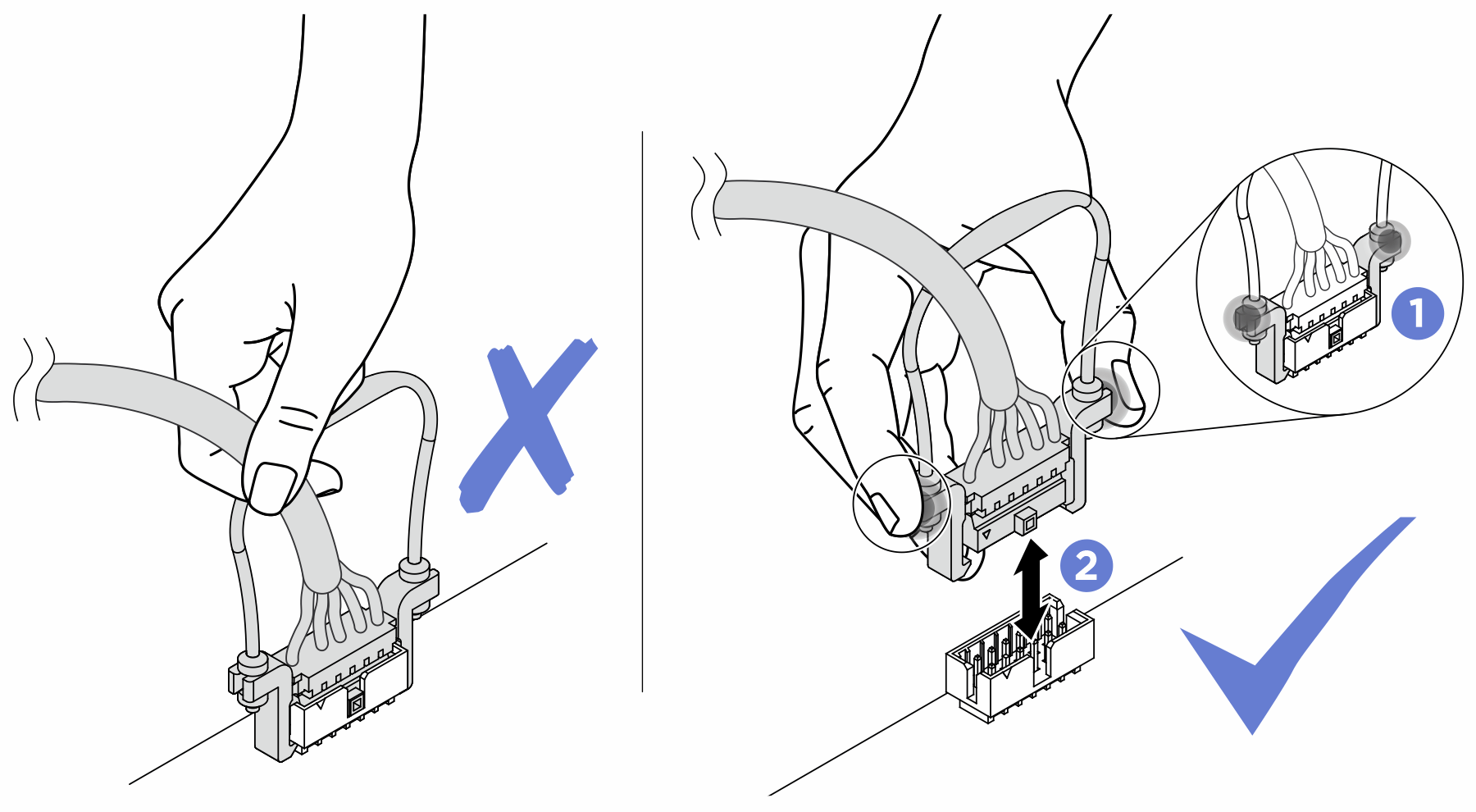
- To disconnect cables from the system board, do as follows:
Press and hold all latches, release tabs, or locks on cable connectors to release the cable connectors.
- Remove the cable connectors vertically or horizontally in alignment with the orientations of the corresponding cable sockets, avoiding any tilt.NoteThe cable connectors might look different from those in the illustration, but the removal procedure is the same.
Following is the list of combinations of cable routing for 2.5-inch drives.
Make sure all the signal cables go through the cable guides.
Figure 1. Cable guide locations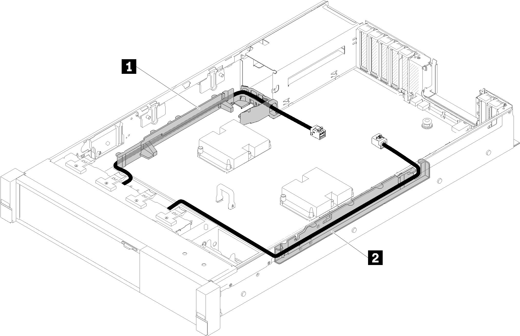
- Connect the direct NVMe signal cables to the NVMe connectors on the processor and memory expansion tray.Figure 2. Connecting NVMe cables to the processor and memory expansion tray
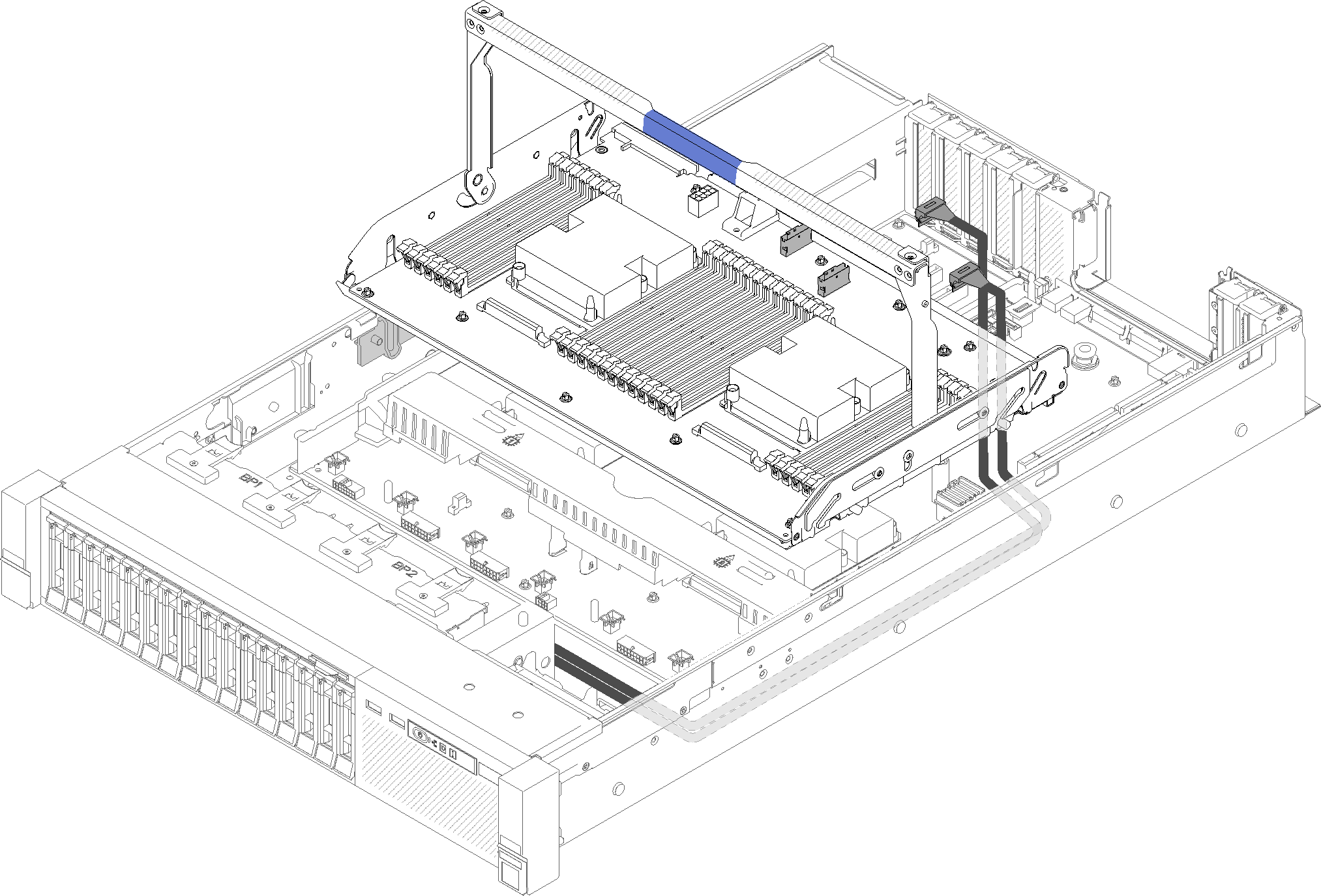
Remove the fan cage assembly (see Remove the fan cage assembly).
Remove the system board air baffle (see Remove the system board air baffle and the power interposer) or the processor and memory expansion tray and the expansion tray air baffle (see Remove the processor and memory expansion tray).
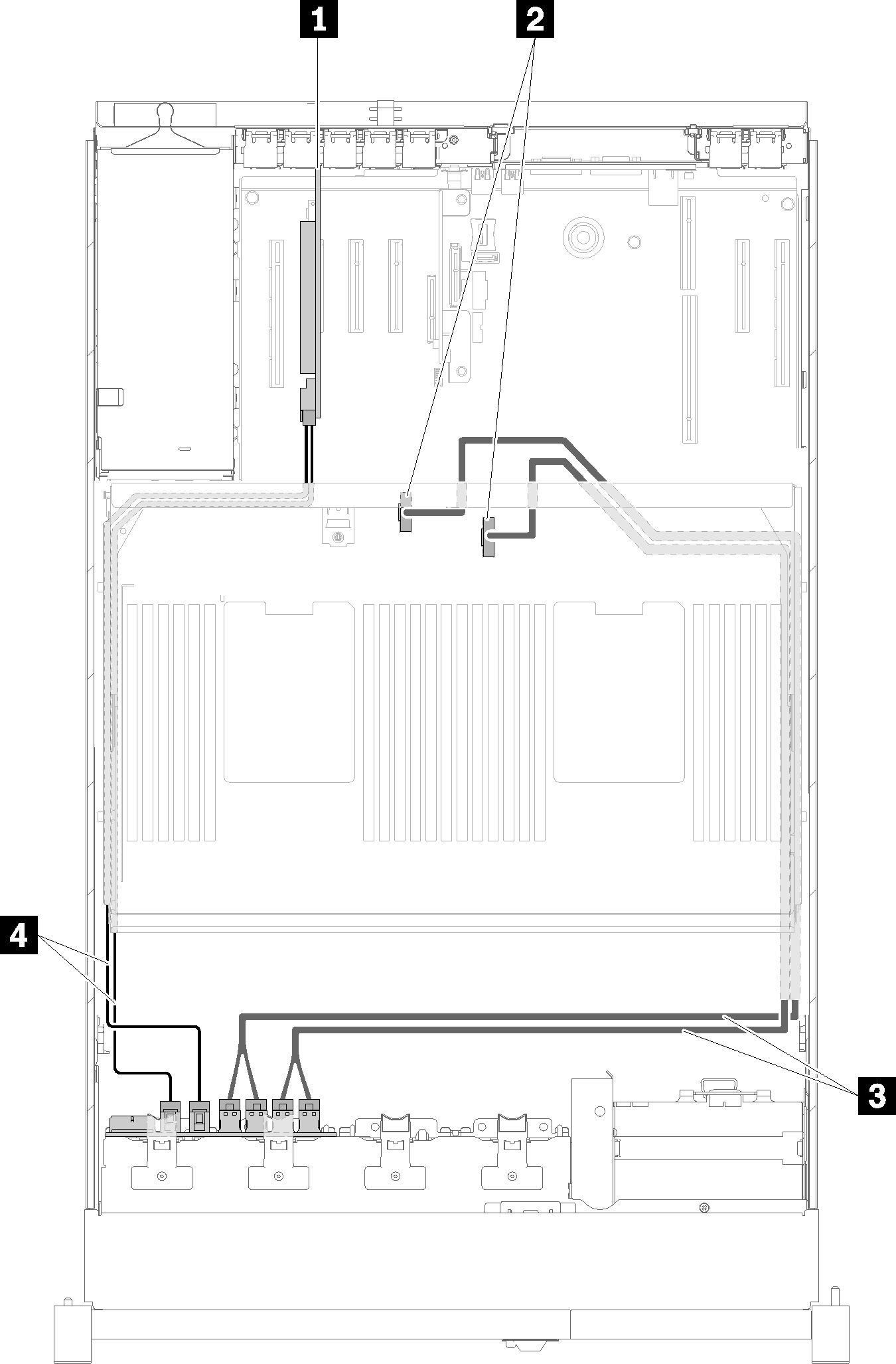
Connecting power cable
Connect power cables for drive backplanes as in the following illustration.
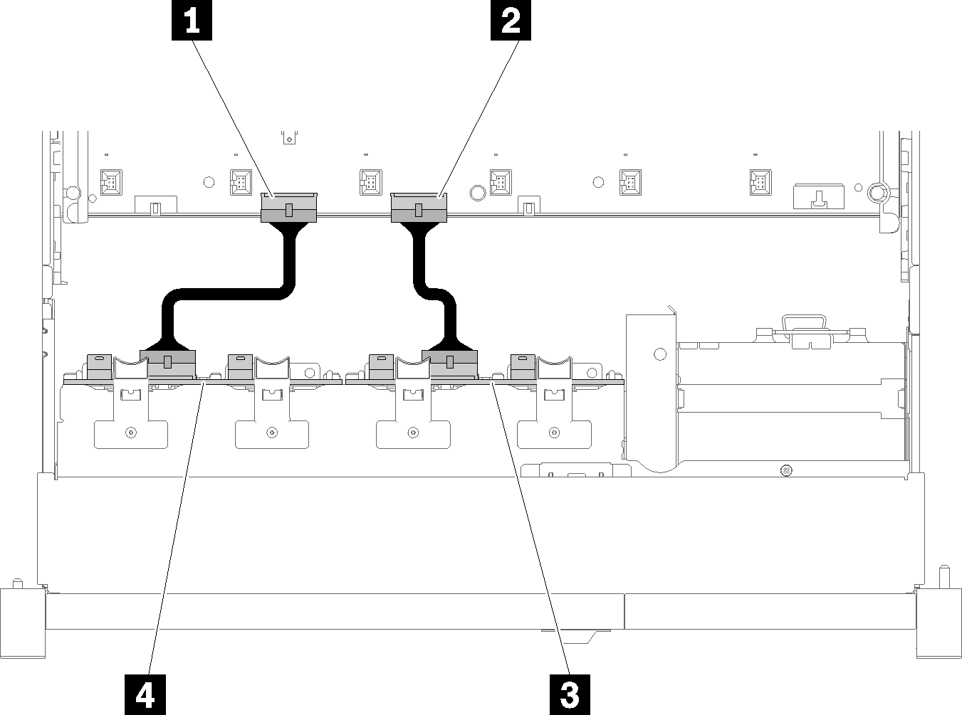
| 1 Power cable connector on the system board | 3 Power cable connector on the drive backplane |
| 2 Power cable connector on the system board | 4 Power cable connector on the drive backplane |
- 2.5-inch SATA/SAS 8-bay backplane (referred to as “8-bay backplane”)
- 2.5-inch AnyBay 8-bay backplane (referred to as “AnyBay backplane”)
Connecting signal cables to one backplane
When one backplane is installed, see the following illustrations for cable routing.
One 8-bay backplane
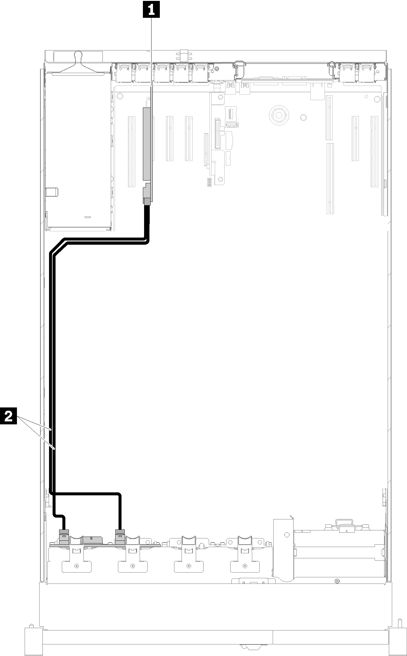
| 1 SATA/SAS RAID adapter (8i) | 2 SATA/SAS signal cables (720 mm) |
One AnyBay backplane
Two processors installed
| 1 PCIe switch card | 3 NVMe signal cables for PCIe switch card |
| 2 SATA/SAS RAID adapter (8i) | 4 SATA/SAS signal cables (720 mm) |
Four processors installed
| 1 SATA/SAS RAID adapter (8i) | 3 Direct NVMe signal cables for processor and memory expansion tray |
| 2 NVMe connectors on the processor and memory expansion tray | 4 SATA/SAS signal cables (720 mm) |
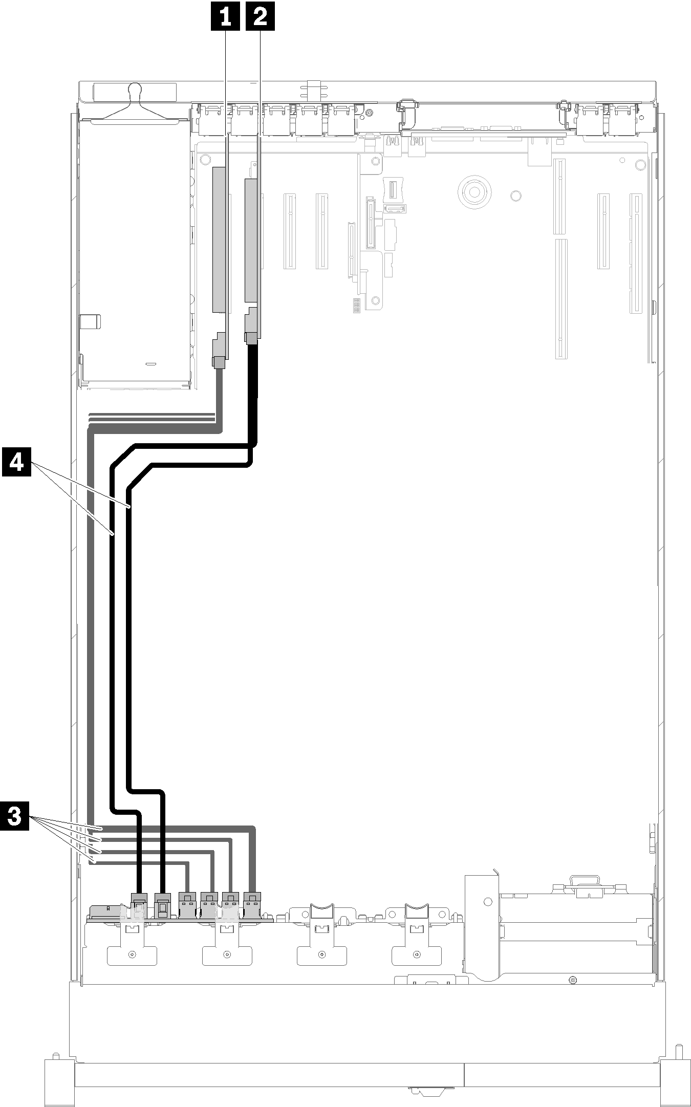
Connecting signal cables to two backplanes
When two backplanes are installed, see the following illustrations for cable routing.
8-bay backplane + 8-bay backplane
Two options are available for this combination:
With SATA/SAS RAID adapter (16i)
Figure 7. Cable routing, 8-bay backplane + 8-bay backplane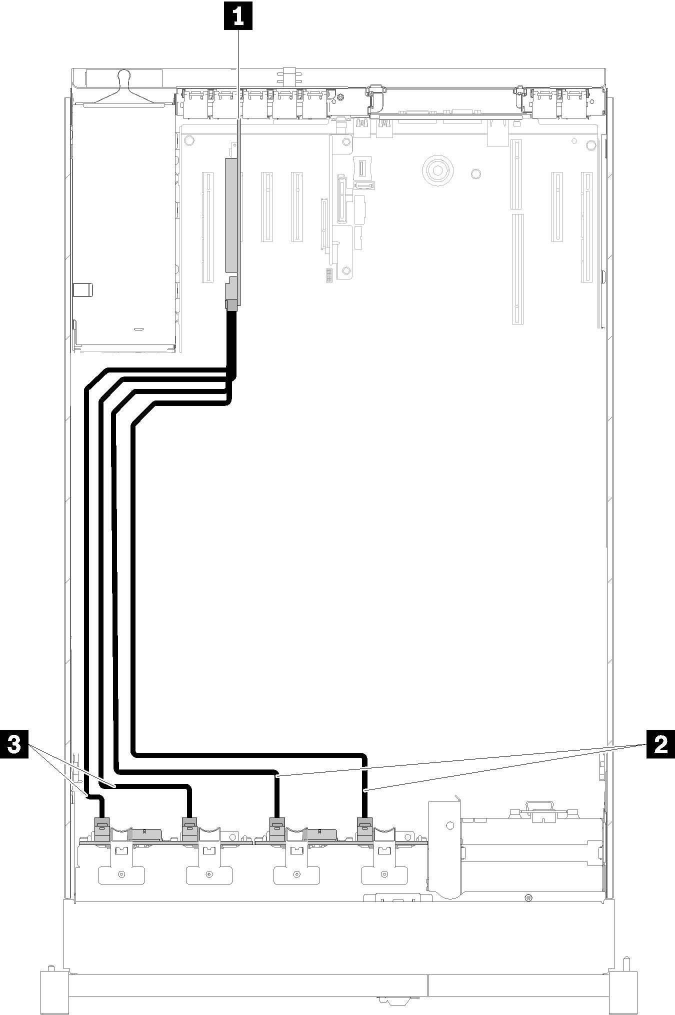
Table 5. Cables and adapters for routing 1 SATA/SAS RAID adapter (16i) 3 SATA/SAS signal cables (720 mm) 2 SATA/SAS signal cables (900 mm) With SATA/SAS RAID adapter (8i)
Figure 8. Cable routing, 8-bay backplane + 8-bay backplane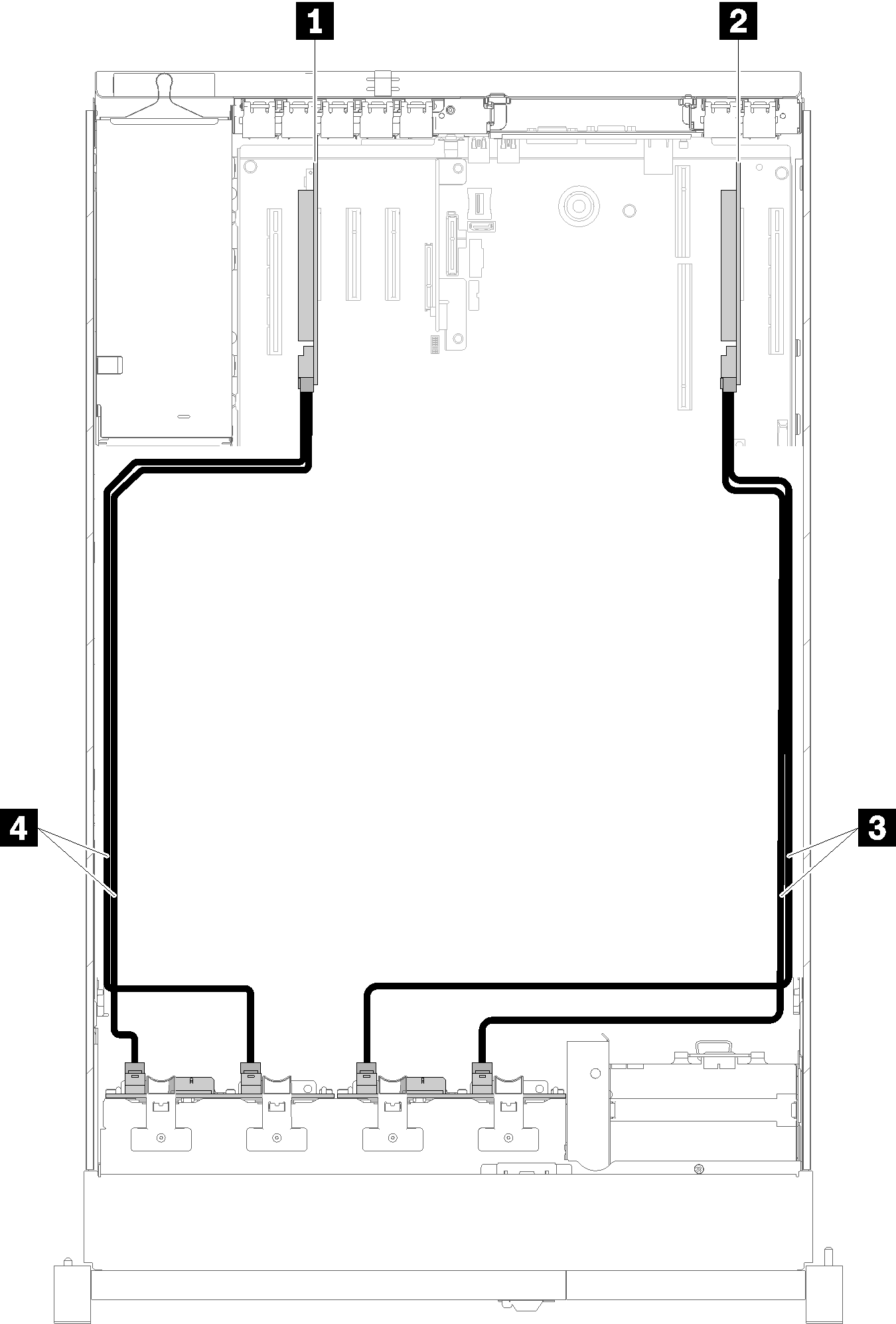
Table 6. Cables and adapters for routing 1 SATA/SAS RAID adapter (8i) 3 SATA/SAS signal cables (720 mm) 2 SATA/SAS RAID adapter (8i) 4 SATA/SAS signal cables (720 mm)
8-bay backplane + AnyBay backplane
- When installing a 8-bay backplane and a AnyBay backplane, always install the 8-bay backplane to drive bay 0-7, and the AnyBay backplane to drive bay 8-15.
- Install the processor and memory expansion tray before connecting the signal cables to NVMe connectors on the expansion tray (see Install the processor and memory expansion tray).
Two processors installed
Two options are available for this combination:
With one SATA/SAS RAID adapter (16i)
Figure 9. Cable routing, 8-bay backplane + AnyBay backplane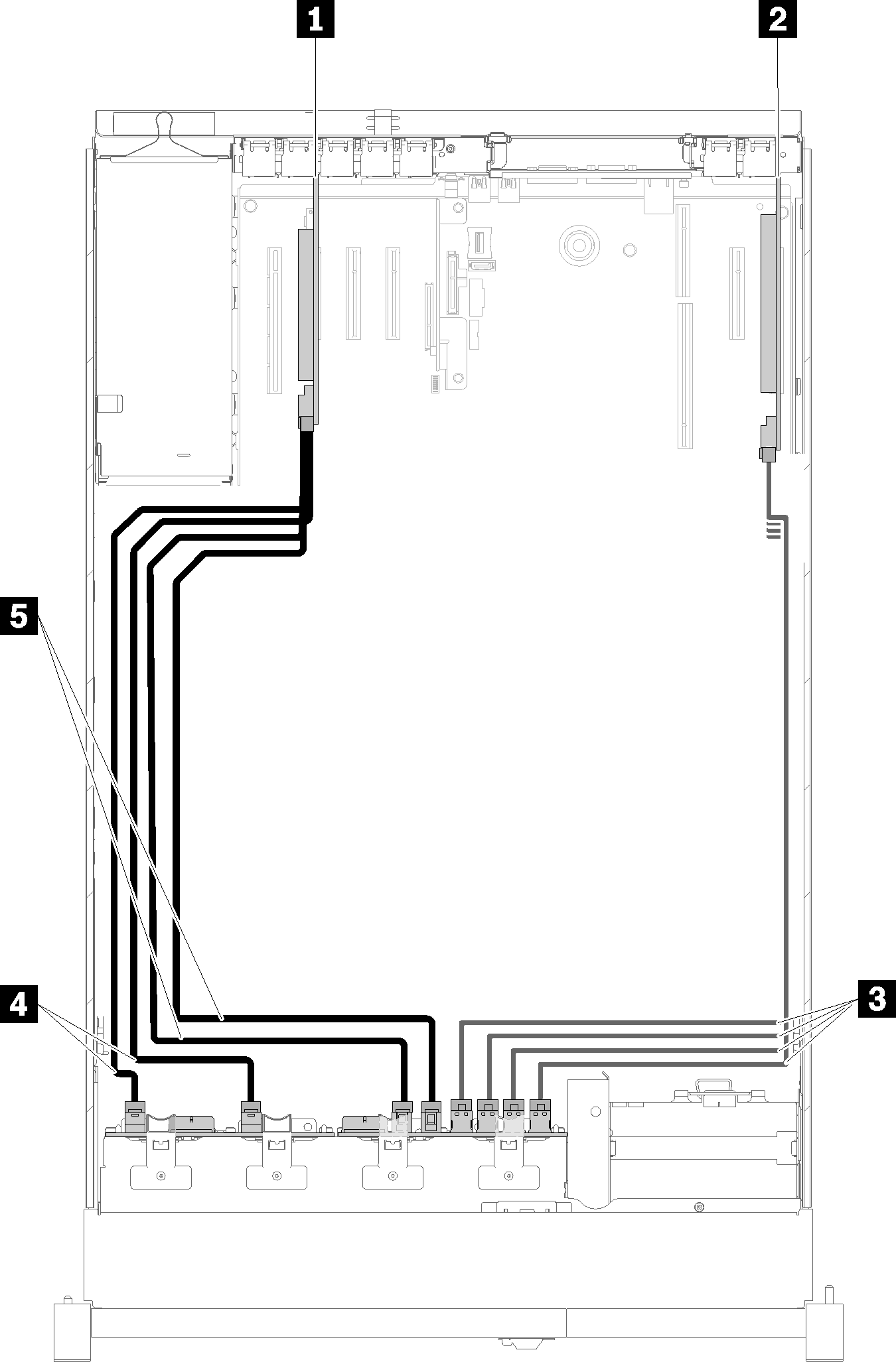
Table 7. Cables and adapters for routing 1 SATA/SAS RAID adapter (16i) 4 SATA/SAS signal cables (720 mm) 2 PCIe switch card 5 SATA/SAS signal cables (900 mm) 3 NVMe signal cables for PCIe switch card With two SATA/SAS RAID adapters (8i)
Figure 10. Cable routing, 8-bay backplane + AnyBay backplane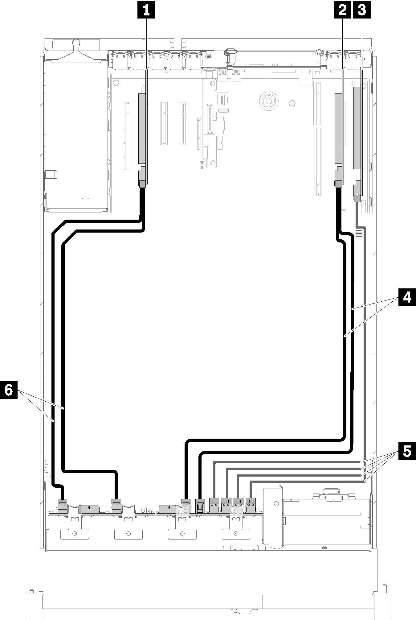
Table 8. Cables and adapters for routing 1 SATA/SAS RAID adapter (8i) 4 SATA/SAS signal cables (720 mm) 2 SATA/SAS RAID adapter (8i) 5 NVMe signal cables for PCIe switch card 3 PCIe switch card 6 SATA/SAS signal cables (720 mm)
Four processors installed
Two options are available for this combination:
With SATA/SAS RAID adapter (16i)
Figure 11. Cable routing, 8-bay backplane + AnyBay backplane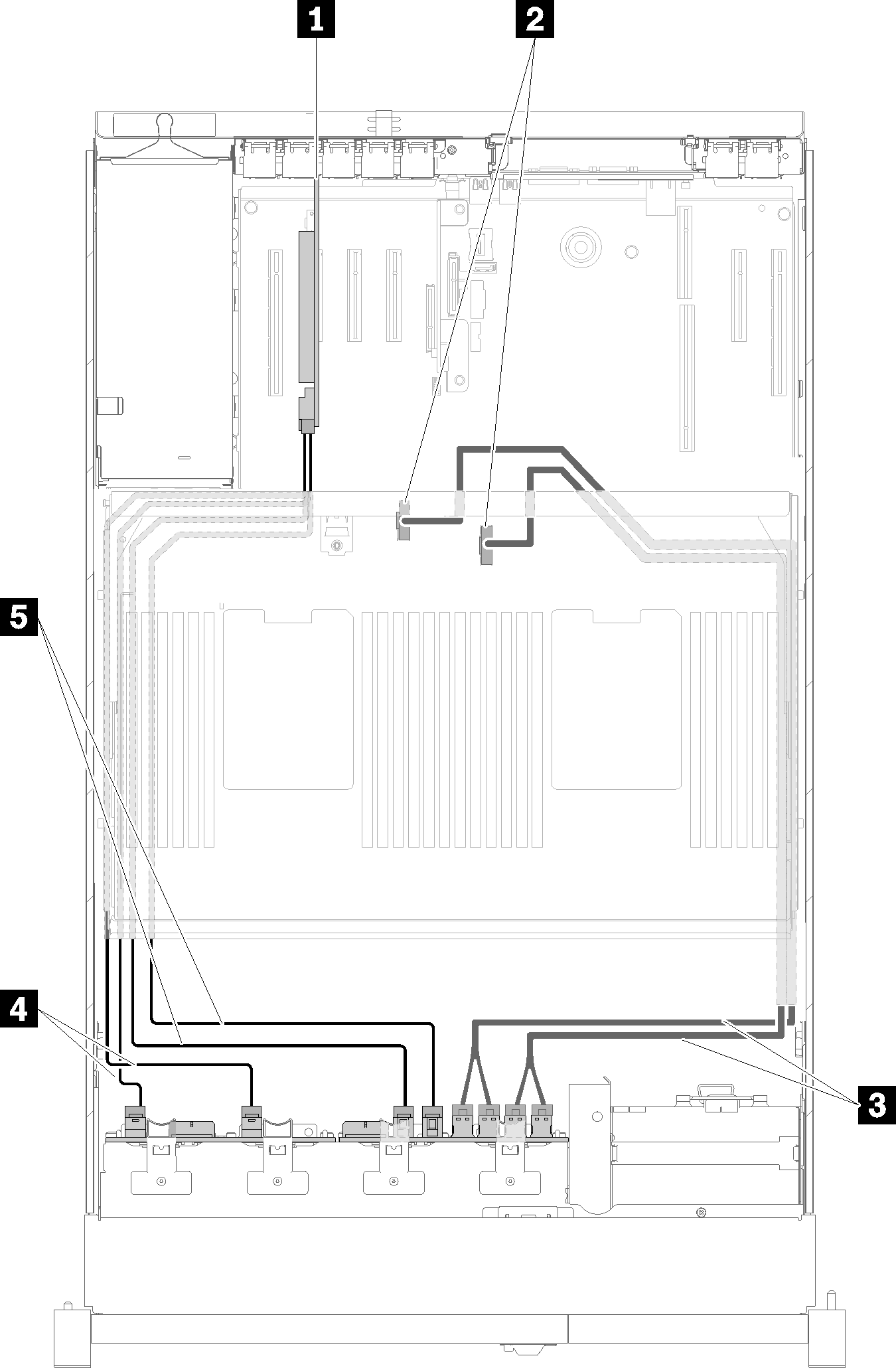
Table 9. Cables and adapters for routing 1 SATA/SAS RAID adapter (16i) 4 SATA/SAS signal cables (720 mm) 2 NVMe connectors on the processor and memory expansion tray 5 SATA/SAS signal cables (900 mm) 3 Direct NVMe signal cables for processor and memory expansion tray With SATA/SAS RAID adapter (8i)
Figure 12. Cable routing, 8-bay backplane + AnyBay backplane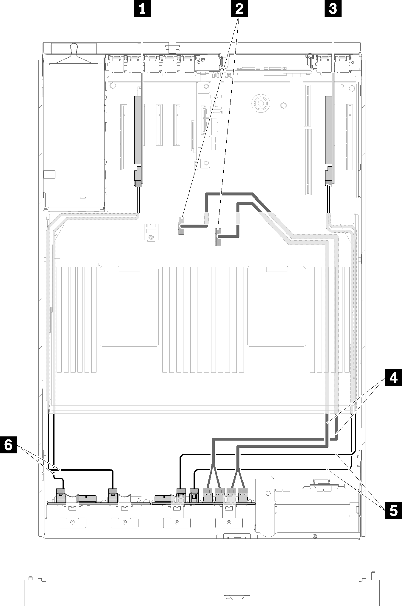
Table 10. Cables and adapters for routing 1 SATA/SAS RAID adapter (8i) 4 Direct NVMe signal cables for processor and memory expansion tray 2 NVMe connectors on the processor and memory expansion tray 5 SATA/SAS signal cables (720 mm) 3 SATA/SAS RAID adapter (8i) 6 SATA/SAS signal cables (720 mm)
AnyBay backplane + AnyBay backplane
Two processors installed
Two options are available for this combination:
With one SATA/SAS RAID adapter (16i)
Figure 13. Cable routing, AnyBay backplane + AnyBay backplane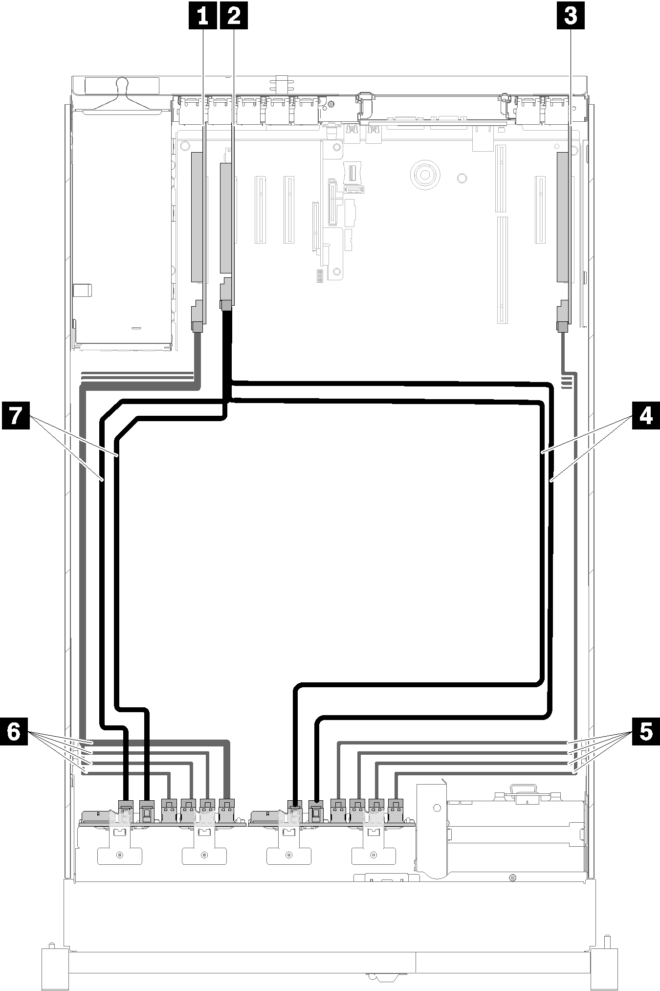
Table 11. Cables and adapters for routing 1 PCIe switch card 5 NVMe signal cables for PCIe switch card 2 SATA/SAS RAID adapter (16i) 6 NVMe signal cables for PCIe switch card 3 PCIe switch card 7 SATA/SAS signal cables (720 mm) 4 SATA/SAS signal cables (900 mm) With two SATA/SAS RAID adapters (8i)
Figure 14. Cable routing, AnyBay backplane + AnyBay backplane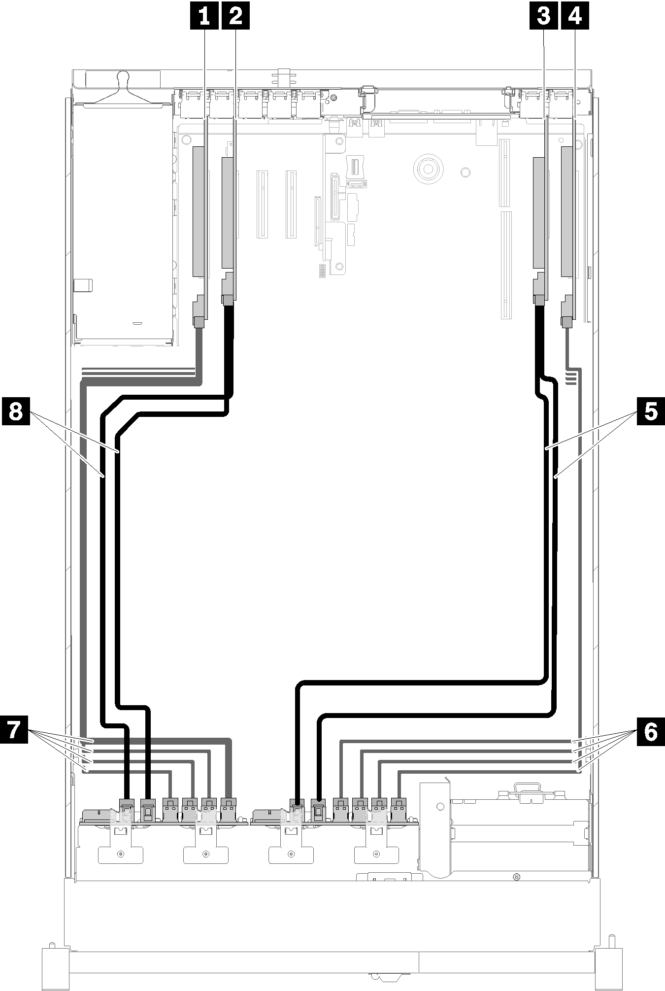
Table 12. Cables and adapters for routing 1 PCIe switch card 5 SATA/SAS signal cables (720 mm) 2 SATA/SAS RAID adapter (8i) 6 NVMe signal cables for PCIe switch card 3 SATA/SAS RAID adapter (8i) 7 NVMe signal cables for PCIe switch card 4 PCIe switch card 8 SATA/SAS signal cables (720 mm)
Four processors installed
Two options are available for this combination:
With one SATA/SAS RAID adapter (16i)
Figure 15. Cable routing, AnyBay backplane + AnyBay backplane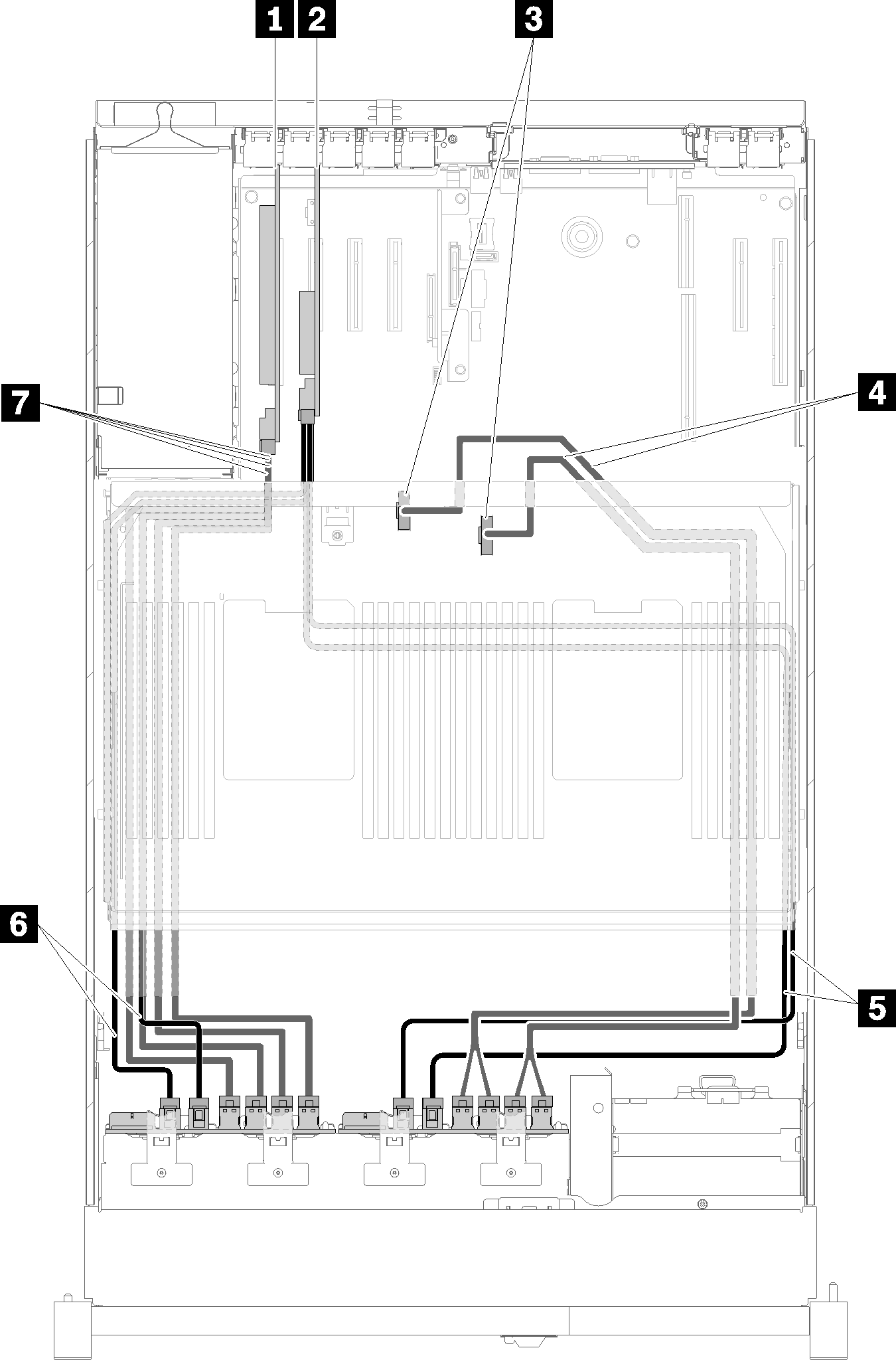
Table 13. Cables and adapters for routing 1 PCIe switch card 5 SATA/SAS signal cables (900 mm) 2 SATA/SAS RAID adapter (16i) 6 SATA/SAS signal cables (720 mm) 3 NVMe connectors on the processor and memory expansion tray 7 NVMe signal cables for PCIe switch card 4 Direct NVMe signal cables for processor and memory expansion tray With two SATA/SAS RAID adapters (8i)
Figure 16. Cable routing, AnyBay backplane + AnyBay backplane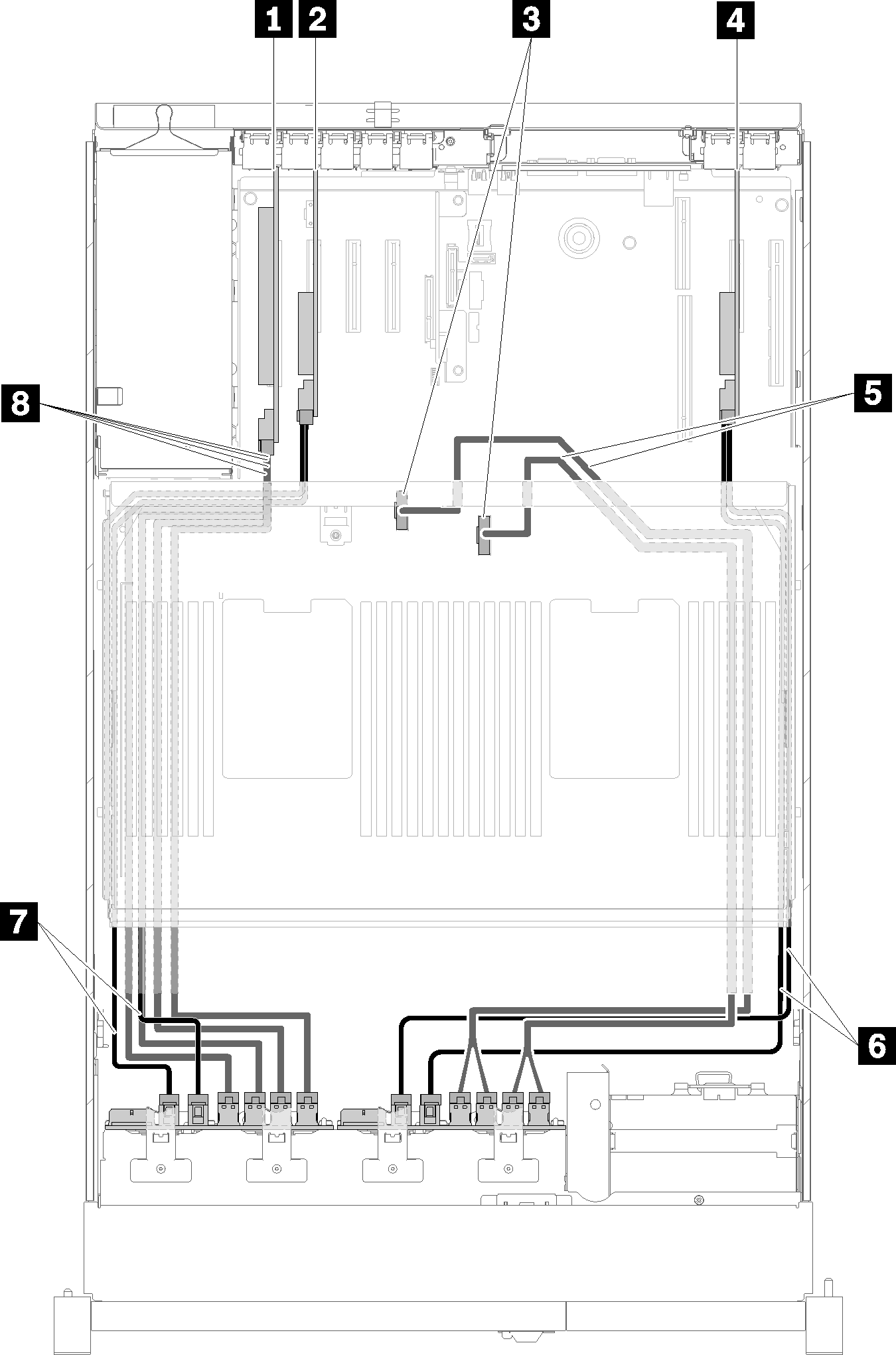
Table 14. Cables and adapters for routing 1 PCIe switch card 5 Direct NVMe signal cables for processor and memory expansion tray 2 SATA/SAS RAID adapter (8i) 6 SATA/SAS signal cables (720 mm) 3 NVMe connectors on the processor and memory expansion tray 7 SATA/SAS signal cables (720 mm) 4 SATA/SAS RAID adapter (8i) 8 NVMe signal cables for PCIe switch card