Remove the system board
Use this procedure to remove the system board.
Before removing the system board:
Record all system configuration information, such as Lenovo XClarity Controller IP addresses, vital product data, and the machine type, model number, serial number, Universally Unique Identifier, and asset tag of the server.
Use the Lenovo XClarity Essentials OneCLI to save the system configuration to external media.
Save the system-event log to external media.
NoteWhen replacing the system board, always update the server with the latest firmware or restore the pre-existing firmware. Make sure that you have the latest firmware or a copy of the pre-existing firmware before you proceed.Read the safety information and installation guidelines (see Safety and Installation Guidelines).
Turn off the server and peripheral devices and disconnect the power cords and all external cables (see Power off the server).
If the server is installed in a rack, remove the server from the rack.
Remove the top cover (see Remove the top cover).
To remove the system board, complete the following steps:
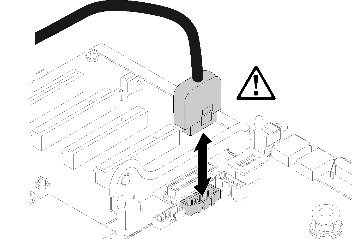
- Disconnect the USB 3.0 cable of operator panel tray assembly and remove it vertically from the system board. Figure 1. Disconnecting USB 3.0 vertically
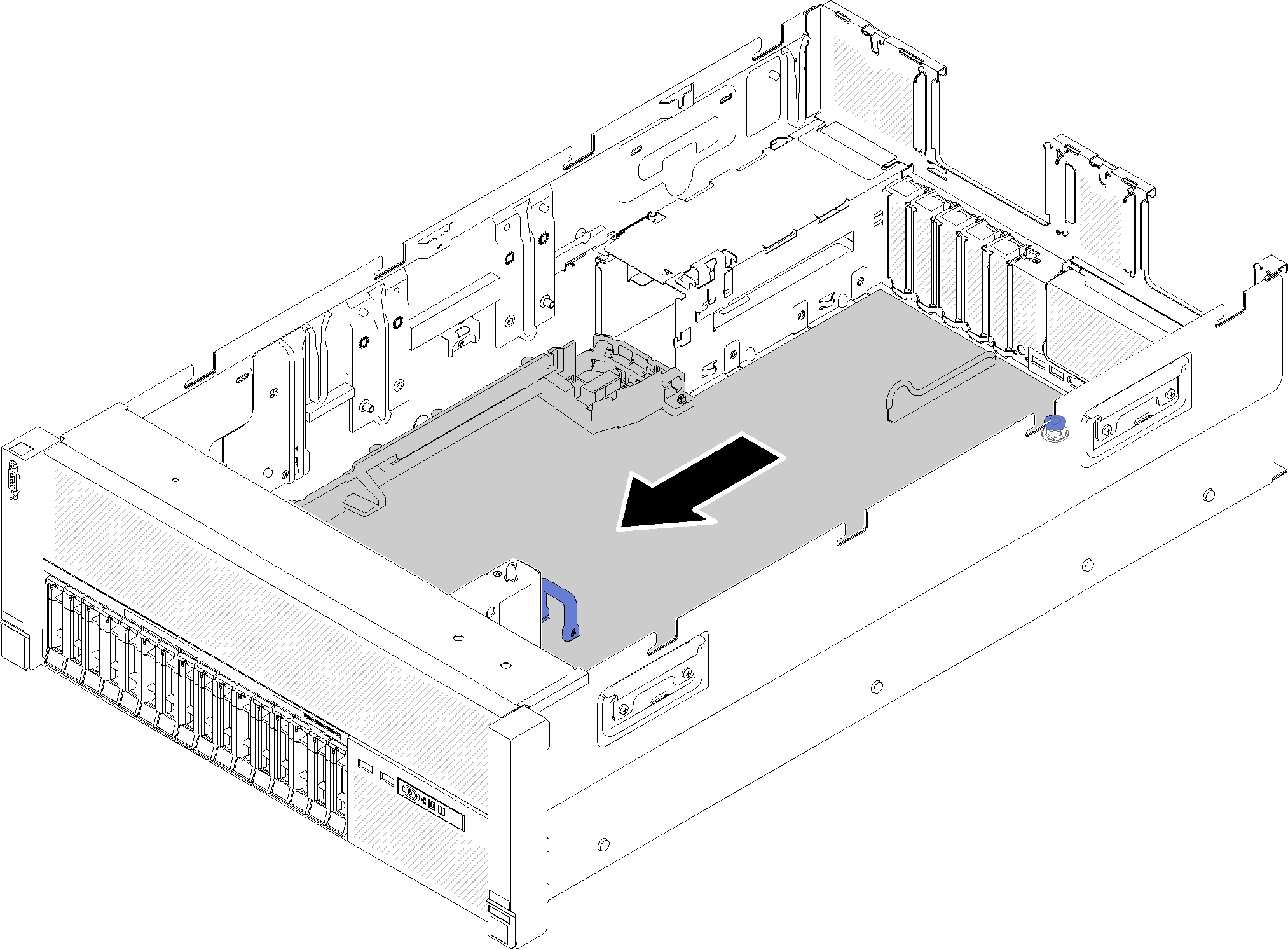
- Grasp the system board handle and thumbnail, and slide the system board toward the front of the server.Figure 2. System board removal
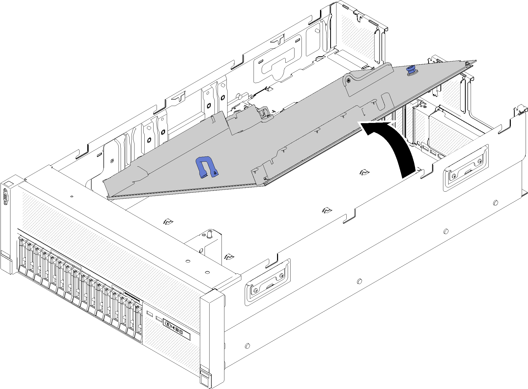
- Rotate the long side of the system board up, and remove the board from the server.Figure 3. System board removal
 NoteThis handle only serves the purpose of removing system board. Do not attempt to lift the whole server with it.
If you are instructed to return the component or optional device, follow all packaging instructions, and use any packaging materials for shipping that are supplied to you.
ImportantBefore you return the system board, make sure that you install the CPU socket covers from the new system board. To replace a CPU socket cover:Take a socket cover from the CPU socket assembly on the new system board and orient it correctly above the CPU socket assembly on the removed system board.
Gently press down the socket cover legs to the CPU socket assembly, pressing on the edges to avoid damage to the socket pins. You might hear a click on the socket cover is securely attached.
Make sure that the socket cover is securely attached to the CPU socket assembly.
If you are planning to recycle the system board, follow the instructions in Disassemble the system board for recycle for compliance with local regulations.
Demo video