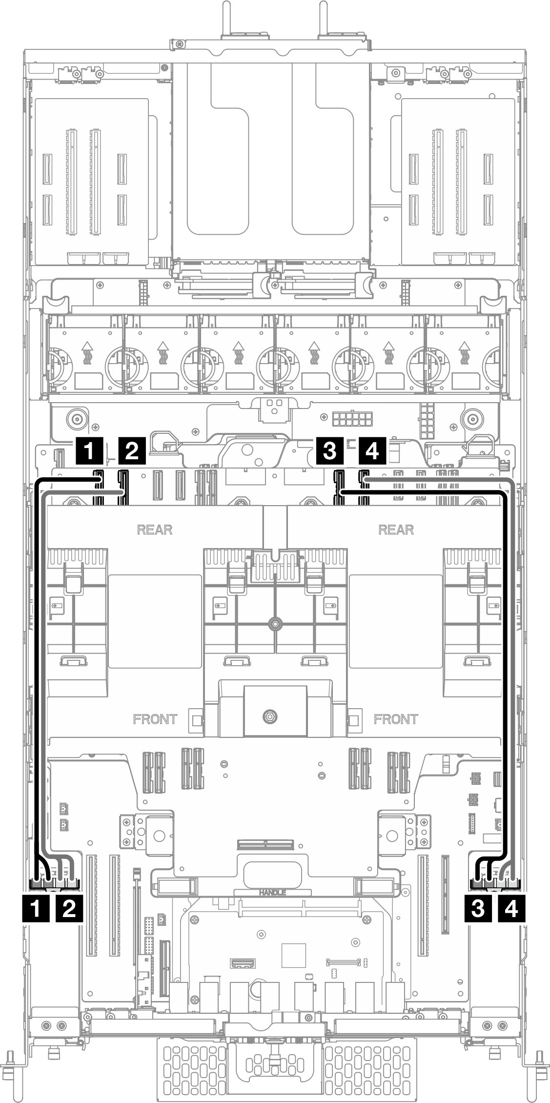
E3.S cable assembly cable routing
Use the section to understand the cable routing for the E3.S cable assembly.
Note
- Connections between connectors; 1↔1, 2↔2, 3↔3, ... n↔n
- When routing the cables, ensure that all cables are routed appropriately through the cable guides.
Figure 1. E3.S cable assembly cable routing


| From | To |
|---|---|
| 1 Left E3.S cable assembly: Drive 0/1 or 8/9 | 1 Upper processor board (CPU BD): PE4AB_L connector |
| 2 Left E3.S cable assembly: Drive 2/3 or 10/11 | 2 Upper processor board (CPU BD): PE4CD_L connector |
| 3 Right E3.S cable assembly: Drive 4/5 or 12/13 | 3 Upper processor board (CPU BD): PE4AB_R connector |
| 4 Right E3.S cable assembly: Drive 6/7 or 14/15 | 4 Upper processor board (CPU BD): PE4CD_R connector |
Give documentation feedback