2.5-inch drive backplane cable routing
Use the section to understand the cable routing for the 2.5-inch drive backplane.
Note
- Connections between connectors; 1↔1, 2↔2, 3↔3, ... n↔n
- When routing the cables, ensure that all cables are routed appropriately through the cable guides.
2.5-inch drive backplane power cable routing
Figure 1. 2.5-inch drive backplane power cable routing (Gen 4 riser) 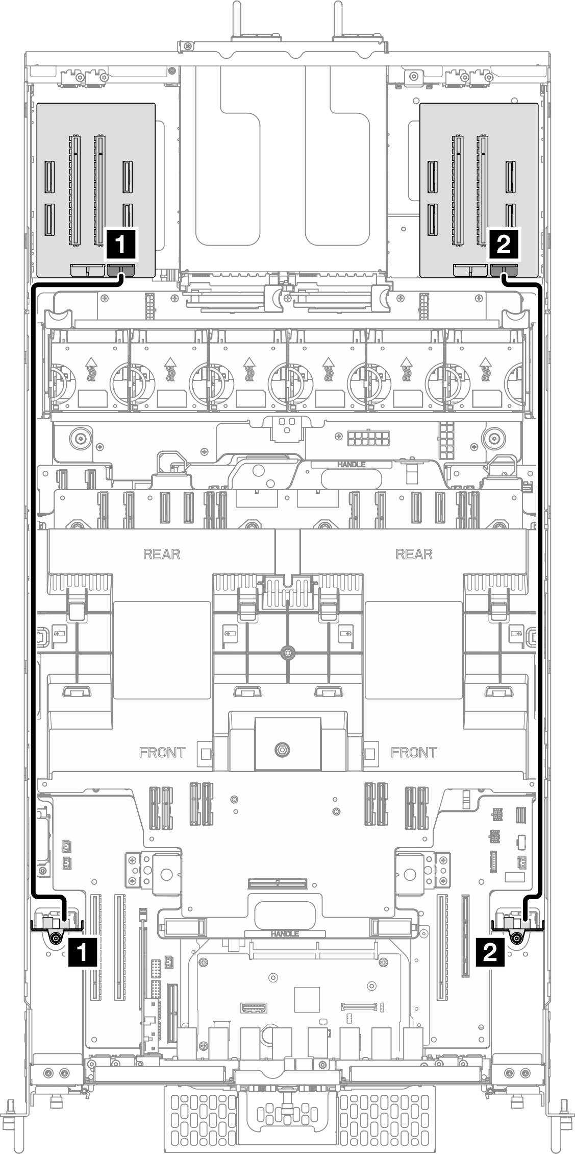 | Figure 2. 2.5-inch drive backplane power cable routing (Gen 5 riser) 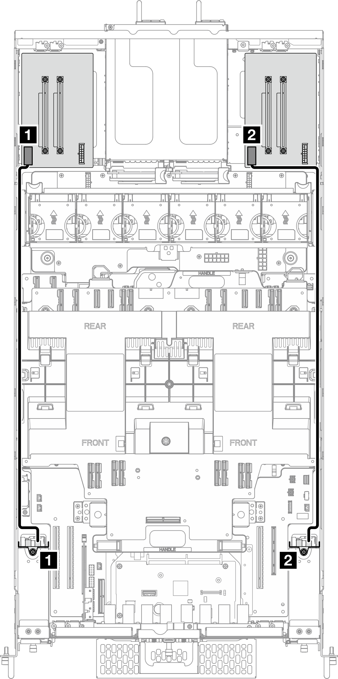 |
| From | To |
|---|---|
| 1 Drive backplane 1: Power connector | 1 Left riser card: Backplane power connector |
| 2 Drive backplane 2: Power connector | 2 Right riser card: Backplane power connector |
One 2.5-inch drive backplane cable routing
Figure 3. One 2.5-inch drive backplane cable routing
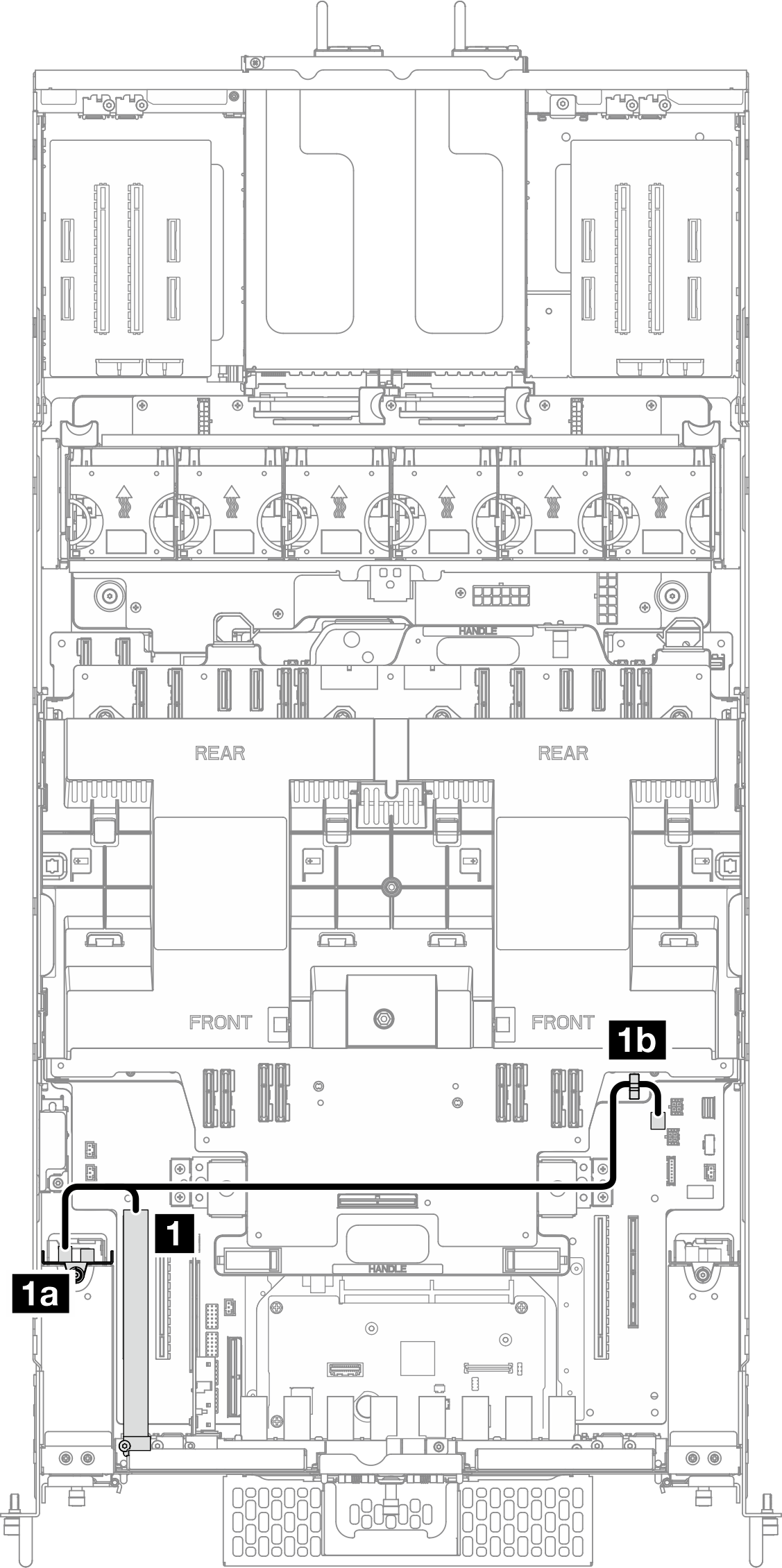
| From | To |
|---|---|
| 1 RAID/HBA adapter | 1a Left drive backplane: Signal connector |
| 1b Cable clip on upper processor board (CPU BD) Note This end of the cable is left unconnected. |
Two 2.5-inch drive backplane cable routing
Figure 4. Two 2.5-inch drive backplane cable routing
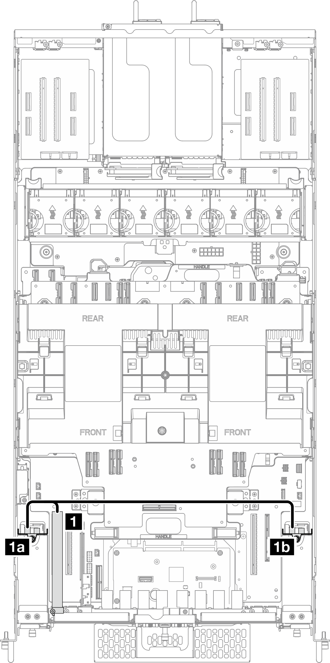
| From | To |
|---|---|
| 1 RAID/HBA adapter | 1a Left drive backplane: Signal connector |
| 1b Right drive backplane: Signal connector |
Give documentation feedback