OCP cable routing
Use the section to understand the cable routing for the OCP module.
Note
- Connections between connectors; 1↔1, 2↔2, 3↔3, ... n↔n
- When routing the cables, ensure that all cables are routed appropriately through the cable guides.
Figure 1. OCP cable routing
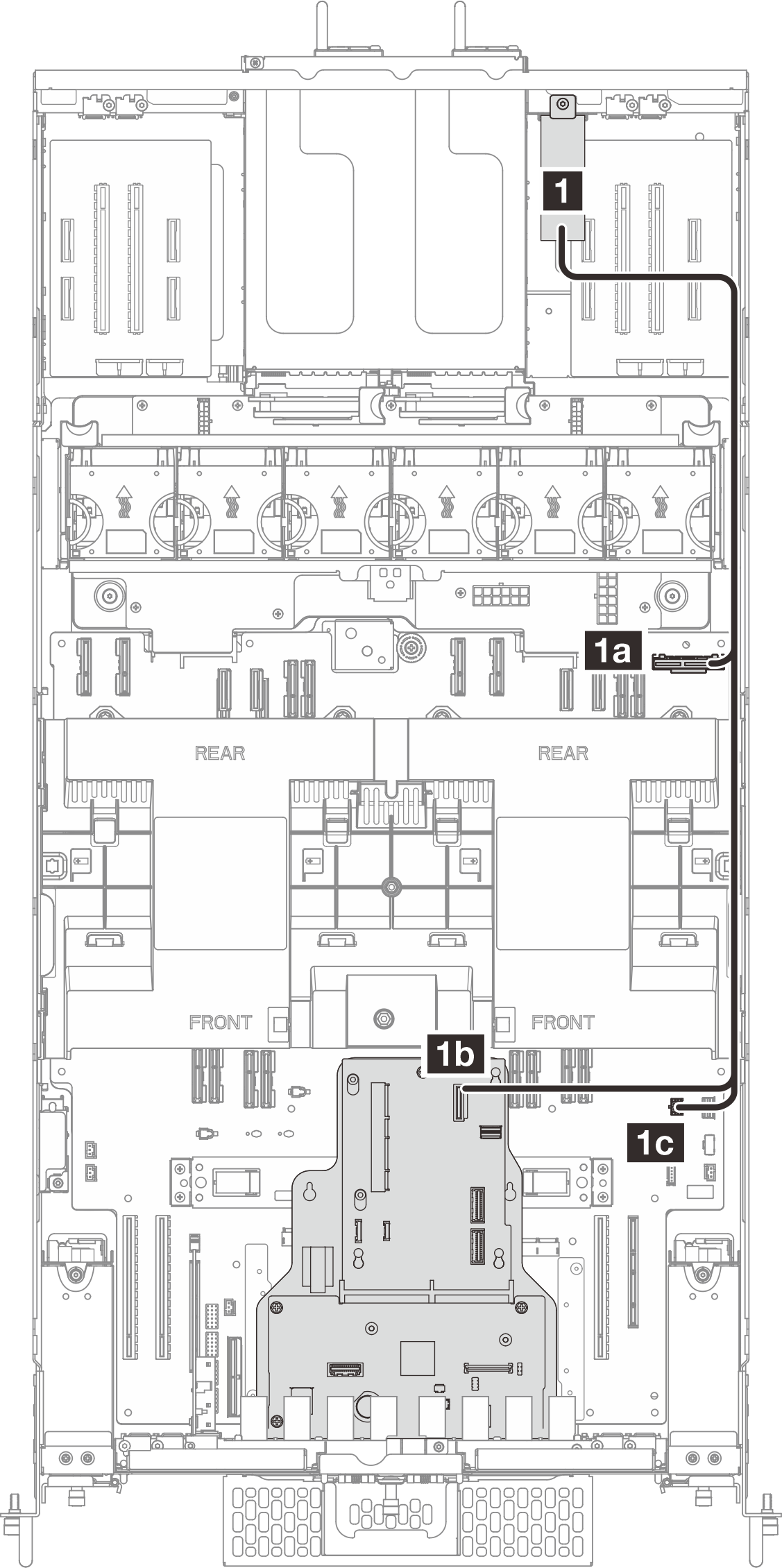
| From | To | Cable |
|---|---|---|
| 1 OCP cage | 1a Lower processor board (MB): Rear OCP connector | Internal OCP (330/750/650 mm) |
| 1b Interposer board : Rear OCP connector | ||
| 1c Lower processor board (MB): Rear OCP power connector |
Give documentation feedback