Memory guidelines
There are a number of criteria that must be followed when selecting and installing memory modules in your server.
The DIMM population sequences in this document show all memory population combinations that are supported by your server. Some of these combinations will perform better than others because they balance the distribution of memory across processors, memory controllers, and memory channels. Balanced memory configurations enable optimal interleaving across all populated memory channels of a processor to boost memory performance.
See the Install a memory module for important information about installing and removing memory. This guide will help with memory selection and planning. More information about optimizing memory performance and configuring memory is available at the Lenovo Press website:
In addition, you can take advantage of a memory configurator tool, which is available at the following site:
Lenovo Enterprise Solutions Configurator (Memory Configurations)
Memory module selection
The following memory modules (DIMMs) are supported for use in the ThinkSystem SR950 server. See Lenovo ServerProven website for specific memory module part numbers and ordering information.
A label on each DIMM identifies the DIMM type. This information is in the format xxxxx nRxxx PC4-xxxxx-xx-xx-xxx. Where n indicates if the DIMM is single-rank (n=1) or dual-rank (n=2).
Installing or removing DIMMs changes the server configuration. When you restart the server, it displays a message that indicates that the memory configuration has changed. There are multiple ways to view the server configuration. See Management options for a description of each management method and how each method applies to various deployment situations.
When you replace a DIMM, the server provides automatic DIMM enablement capability without requiring you to use the Lenovo XClarity Provisioning Manager to enable the new DIMM manually.
Memory architecture
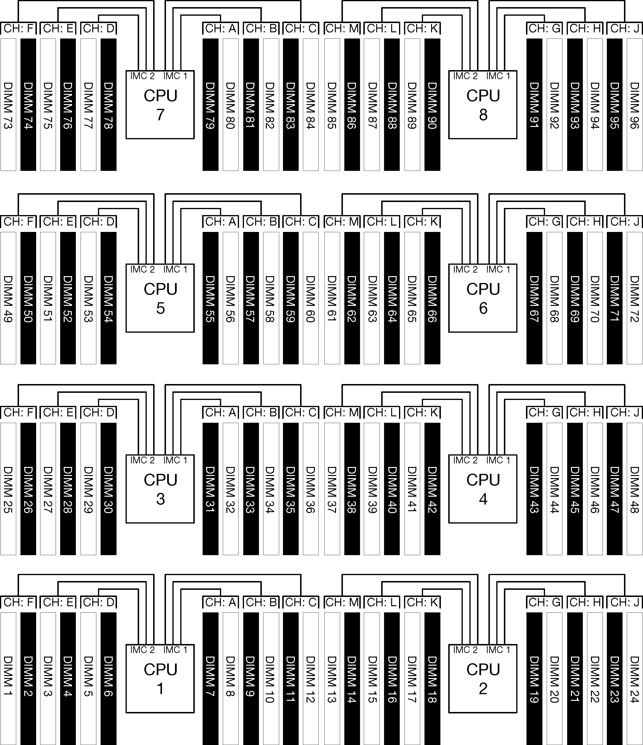
The relationship between memory controllers, channels, and connectors on each system board is shown in the following illustration and each memory channel has two DIMM slots (0, furthest from the processor, and 1, closest to the processor).
Each processor in your server has two memory controllers: IMC1 and IMC2.
Each memory controller has three memory channels:
Processor 1:
IMC1 has memory channels A, B, and C.
IMC2 has memory channels D, E, and F.
Processor 2:
IMC1 has memory channels G, H, and J.
IMC2 has memory channels K, L, and M.
Each memory channel has two DIMM slots: slot 0 (furthest from the processor) and slot 1 (closest to the processor).
Memory modules population requirements
Observe the following rules when populating memory modules for all memory modes.
Install memory modules following only the sequences shown in Memory module installation rules and order.
Do not mix R-DIMMs, LR-DIMMs, and 3DS DIMMs in a server.
At least one DIMM is required for each processor. Install at least six DIMMs per processor for good performance.
An “M” SKU processor is required for processors with more than six 128GB DIMMs installed.
Within a memory controller:
Populate channel A/D first. Channel B/E will be either empty or must be identically populated as channel A/D. Channel C/F will be either empty or must be identically populated as channel B/E.
NoteFive DIMM configurations is a supported exception to these population rules. Five DIMMs are populated so channels 0 and 1 each have two DIMMs and channel 2 has one DIMM.Populate the memory connector in each channel that is physically furthest from the processor (slot 0) first.
If a memory channel has two DIMMs installed and these DIMMs have different numbers of ranks, populate the DIMM with higher number of ranks in the memory connector that is physically furthest from the processor (slot 0).
If two DIMMs on a channel have identical ranks, populate the DIMM with higher capacity in the memory connector that is physically furthest from the processor (slot 0).
Populating memory modules for best system performance
To populate memory configurations for the best memory performance, observe the following general guidelines for all memory modes.
When multiple processors are installed, all processors within the server must have identical memory population.
Populate all memory channels for optimal performance.
If a processor has only three DIMMs that are identical (same Lenovo part number), populate all of them in memory controller 1 (IMC1).
Additional requirements for memory mirroring
The following rules apply for memory mirroring.
The server supports only two, three, four, or six DIMMs per memory controller (one or five DIMMs per memory controller is not supported).
As with independent memory mode, equal DIMM sizes must be installed for the populated memory channels. DIMM slot population within a channel does not have to be identical; however, the same DIMM slot locations across channel A/B/C or channels D/E/F must be populated identically.
If DIMMs are installed in only two memory channels, mirroring occurs across two DIMMs. Channels A/D and B/E hold the primary and secondary cache lines.
If DIMMs are installed in all three memory channels, mirroring occurs across all three DIMM channels. Channels A/D and B/E, Channels B/E and C/F, and Channels C/F and A/D hold the primary and secondary cache lines.
Do not mix 2-channel and 3-channel DDR mirroring in a memory controller.
Additional requirements for memory sparing
The following rules apply for memory sparing:
As with independent memory mode, all memory channels must have at least two ranks.
Every populated memory channel must have at least two ranks of DIMMs.
If a memory channel has only single rank DIMMs, populate both single rank DIMMs on one channel.
Single DIMM-per-channel systems do not support single-rank DIMMs in sparing mode.